DRIVING SUPPORT ECU INSTALLATION
CAUTION / NOTICE / HINT
Tech Tips
A bolt without a torque specification is shown in the standard bolt chart Click here.
PROCEDURE
-
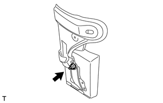
INSTALL DRIVING SUPPORT ECU ASSEMBLY
-
Install the driving support ECU assembly with the nut.
Note
-
Do not use a driving support ECU assembly which has been dropped or subjected to any strong shocks.
-
During the removal and installation, do not remove the drip-proof cover.
-
When a new driving support ECU assembly is installed, perform initialization.
-
-
-
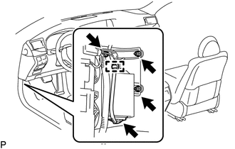
INSTALL DASH PANEL EXTENSION LH
-
Connect the connector.
-
Install the dash panel extension LH and driving support ECU assembly as a unit with the 2 nuts and bolt.
-
Attach the wire harness clamp.
-
for RHD:
Return the floor carpet to its original position.
-
-
INSTALL NO. 3 DASH PANEL INSULATOR PAD (for LHD)
-
Install the No. 3 dash panel insulator pad.
-
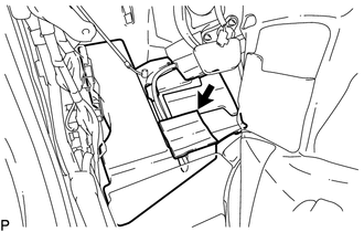
Connect the No. 2 cooler unit drain hose.
-
Clean the No. 3 dash panel insulator pad surface.
-
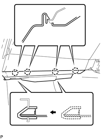
Attach a new No. 1 cooling unit packing in the position shown in the illustration.
-
Return the floor carpet to its original position.
-
Attach the clamp.
-
-
INSTALL ACCELERATOR PEDAL SENSOR ASSEMBLY (for LHD)
-
INSTALL COWL SIDE TRIM BOARD LH
-
INSTALL FRONT DOOR SCUFF PLATE LH
-
INSTALL NO. 1 INSTRUMENT PANEL UNDER COVER SUB-ASSEMBLY (for LHD)
-
INSTALL NO. 2 INSTRUMENT PANEL UNDER COVER SUB-ASSEMBLY (for RHD)
-
Connect the connector.
-
Insert the 2 guides.
-
Attach the 4 claws to install the No. 2 instrument panel under cover sub-assembly.
-