DYNAMIC RADAR CRUISE CONTROL SYSTEM ECU Power Source Circuit
DESCRIPTION
This circuit provides power to operate the driving support ECU.
WIRING DIAGRAM
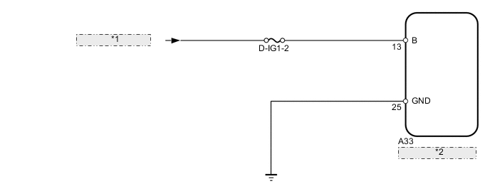
| *1 | from D-IG1-1 Relay |
| *2 | Driving Support ECU |
PROCEDURE
-
CHECK FUSE (D-IG1-2)
-
Remove the D-IG1-2 fuse from the main body ECU.
-
Measure the resistance according to the value(s) in the table below.
Standard Resistance Tester Connection Condition Specified Condition D-IG1-2 fuse Always Below 1 Ω
NG 
REPLACE FUSE
OK 
-
-
CHECK HARNESS AND CONNECTOR (DRIVING SUPPORT ECU - BATTERY AND BODY GROUND)
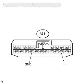
*1 Front view of wire harness connector: (to Driving Support ECU)
-
Disconnect the A33 ECU connector.
-
Measure the voltage according to the value(s) in the table below.
Standard Voltage Tester Connection Switch Condition Specified Condition A33-13 (B) - Body ground Power switch ON (IG) 11 to 14 V A33-13 (B) - Body ground Power switch OFF Below 1 V -
Measure the resistance according to the value(s) in the table below.
Standard Resistance Tester Connection Condition Specified Condition A33-25 (GND) - Body ground Always Below 1 Ω
OK
PROCEED TO NEXT CIRCUIT INSPECTION SHOWN IN PROBLEM SYMPTOMS TABLE Click here
NG
REPAIR OR REPLACE HARNESS OR CONNECTOR
-