HYBRID CONTROL SYSTEM, Diagnostic DTC:P0722-854
| DTC Code | DTC Name |
|---|---|
| P0722-854 | Output Speed Sensor Circuit No Signal |
DESCRIPTION
The transmission revolution sensor (SP2) sends the output shaft rotation speed signal to the hybrid vehicle control ECU.
| DTC No. | INF Code | DTC Detection Condition | Trouble Area |
|---|---|---|---|
| P0722 | 854 | Pulses are not input from the transmission revolution sensor (SP2) to the hybrid vehicle control ECU when the velocity of the vehicle (calculated from the engine speed and MG2 speed) is more than the specified value. |
|
WIRING DIAGRAM
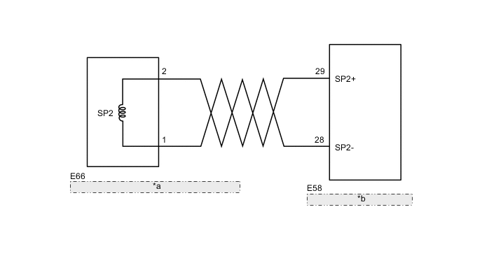
| *a | Hybrid Vehicle Transmission Assembly (Transmission Revolution Sensor (SP2)) |
| *b | Hybrid Vehicle Control ECU |
CAUTION / NOTICE / HINT
Tech Tips
Driving at speeds above 40 km/h (25 mph) will make this problem easier to reproduce. There is a possibility that the speed of the vehicle will change rapidly (deceleration may occur) when the DTC is detected. For this reason it is preferable to use a chassis dynamometer (4WD type) when trying to reproduce this problem.
PROCEDURE
-
CHECK CONNECTOR CONNECTION CONDITION (HYBRID VEHICLE CONTROL ECU CONNECTOR)
-
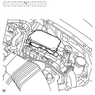
*1 Hybrid Vehicle Control ECU Check the connections of the hybrid vehicle control ECU connectors.
OK The connectors are connected securely and there are no contact problems.
NG 
CONNECT SECURELY
OK 
-
-
CHECK TRANSMISSION REVOLUTION SENSOR (SP2)
-
Turn the power switch off.
-
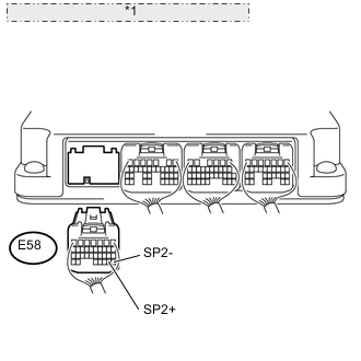
*1 Rear view of wire harness connector: (to Hybrid Vehicle Control ECU) Disconnect connector E58 from the hybrid vehicle control ECU.
-
Measure the resistance according to the value(s) in the table below.
Standard resistance Tester Connection Condition Specified Condition E58-29 (SP2+) - E58-28 (SP2-) Approximately -30°C (-22° F) 450 to 546 Ω
(Reference)
Approximately 20°C (68° F) 560 to 680 Ω Approximately 80°C (176° F) 692 to 840 Ω
(Reference)
NG 
CHECK CONNECTOR CONNECTION CONDITION (TRANSMISSION REVOLUTION SENSOR (SP2) CONNECTOR) Click here
OK
-
-
CHECK HYBRID VEHICLE CONTROL ECU (CHECK WAVEFORM)
-
Connect connector E58 to the hybrid vehicle control ECU.
-
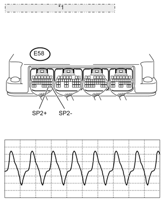
*1 Component with harness connected: (Hybrid Vehicle Control ECU) Connect an oscilloscope between the hybrid vehicle control ECU terminals specified in the following table, and measure the waveform.
Item Contents Terminal E58-28 (SP2-) - E58-29 (SP2+) Equipment Setting 2 V/DIV., 2 ms./DIV. Condition Driving at approximately 55 km/h (34 mph) Tech Tips
The higher the vehicle speed, the shorter the cycle and higher the voltage.
NG
REPLACE HYBRID VEHICLE TRANSMISSION ASSEMBLY Click here
OK
-
-
CHECK FOR INTERMITTENT PROBLEMS
-
Check for intermittent problems Click here.
OK
REPLACE HYBRID VEHICLE CONTROL ECU Click here
NG
REPAIR OR REPLACE MALFUNCTIONING PARTS, COMPONENT AND AREA
-
-
CHECK CONNECTOR CONNECTION CONDITION (TRANSMISSION REVOLUTION SENSOR (SP2) CONNECTOR)
-
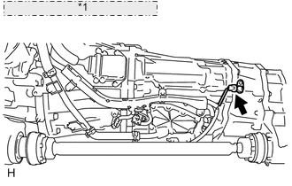
*1 Transmission Revolution Sensor Check the connection of the transmission revolution sensor (SP2) connector.
OK The connector is connected securely and there are no contact problems.
NG
CONNECT SECURELY
OK
-
-
CHECK HARNESS AND CONNECTOR (TRANSMISSION REVOLUTION SENSOR - HYBRID VEHICLE CONTROL ECU)
-
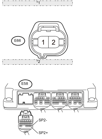
*1 Front view of wire harness connector: (to Transmission Revolution Sensor) *2 Rear view of wire harness connector: (to Hybrid Vehicle Control ECU) Disconnect the transmission revolution sensor (SP2) connector.
-
Turn the power switch on (IG).
-
Measure the voltage according to the value(s) in the table below.
Standard voltage Tester Connection Switch Condition Specified Condition E58-28 (SP2-) - Body ground Power switch on (IG) Below 1 V E58-29 (SP2+) - Body ground Power switch on (IG) Below 1 V Note
Turning the power switch on (IG) with the hybrid vehicle control ECU connector disconnected causes other DTCs to be stored. Clear the DTCs after performing this inspection.
-
Turn the power switch off.
-
Measure the resistance according to the value(s) in the table below.
Standard resistance (Check for open) Tester Connection Switch Condition Specified Condition E58-28 (SP2-) - E66-1 Power switch off Below 1 Ω E58-29 (SP2+) - E66-2 Power switch off Below 1 Ω Standard resistance (Check for short) Tester Connection Switch Condition Specified Condition E58-28 (SP2-) or E66-1 - Body ground and other terminals Power switch off 10 kΩ or higher E58-29 (SP2+) or E66-2 - Body ground and other terminals Power switch off 10 kΩ or higher Tech Tips
The transmission revolution sensor is not available separately. If it requires replacement, replace the hybrid vehicle transmission assembly.
OK
REPLACE HYBRID VEHICLE TRANSMISSION ASSEMBLY Click here
NG
REPAIR OR REPLACE HARNESS OR CONNECTOR
-