HYBRID CONTROL SYSTEM, Diagnostic DTC:P0516-769, P0517-770
| DTC Code | DTC Name |
|---|---|
| P0516-769 | Battery Temperature Sensor Circuit Low |
| P0517-770 | Battery Temperature Sensor Circuit High |
DESCRIPTION
-
The auxiliary battery temperature sensor detects the auxiliary battery temperature. The resistance of the thermistor built into the auxiliary battery temperature sensor changes in accordance with changes in the auxiliary battery temperature. The lower the auxiliary battery temperature, the higher the thermistor resistance. Conversely, the higher the temperature, the lower the resistance. The auxiliary battery temperature sensor is connected to the hybrid vehicle control ECU. A voltage of 5 V is supplied to the auxiliary battery temperature sensor from the THB terminal of the hybrid vehicle control ECU through its internal resistor R. This means that resistor R and the auxiliary battery temperature sensor are connected in series. The voltage at the THB terminal and the resistance value change in accordance with changes in the auxiliary battery temperature. Based on this signal, the hybrid vehicle control ECU reduces the charging current when the auxiliary battery temperature is high to protect the auxiliary battery.
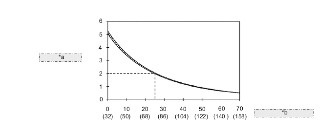
*a Resistance (kΩ) *b Temperature (°C (°F))
| DTC No. | INF Code | DTC Detection Condition | Trouble Area |
|---|---|---|---|
| P0516 | 769 | Malfunction in the auxiliary battery temperature sensor circuit (short to GND) |
|
| P0517 | 770 | Malfunction in the auxiliary battery temperature sensor circuit (open or short to +B) |
WIRING DIAGRAM
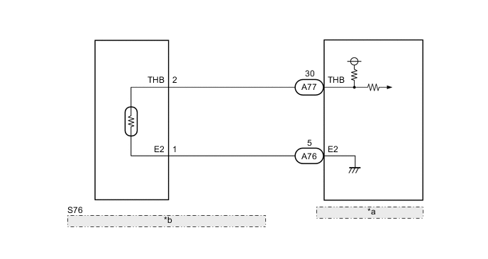
| *a | Hybrid Vehicle Control ECU |
| *b | Auxiliary Battery (Battery Temperature Sensor) |
CAUTION / NOTICE / HINT
Tech Tips
-
Read the freeze frame data using the intelligent tester. In the freeze frame data, some information is recorded about the engine conditions at the moment a malfunction occurred. This information can be helpful when troubleshooting.
-
Characteristics of the thermistor resistance (reference values) are as follows.
Terminal THB
(with connector disconnected)
Resistance Ambient Temperature THB - E2 4.5 to 5.5 V 5.0 to 5.3 kΩ Approximately 0°C (32°F) 2.3 to 2.5 kΩ Approximately 20°C (68°F) 1.1 to 1.3 kΩ Approximately 40°C (104°F)
PROCEDURE
-
CHECK CONNECTOR CONNECTION CONDITION (HYBRID VEHICLE CONTROL ECU CONNECTOR)
-
Check the connections of the hybrid vehicle control ECU connectors.
OK The connectors are connected securely and there are no contact problems.
NG 
CONNECT SECURELY
OK 
-
-
CHECK CONNECTOR CONNECTION CONDITION (BATTERY TEMPERATURE SENSOR CONNECTOR)
-
Check the connection of the battery temperature sensor connector.
OK The connector is connected securely and there are no contact problems.
NG
CONNECT SECURELY
OK
-
-
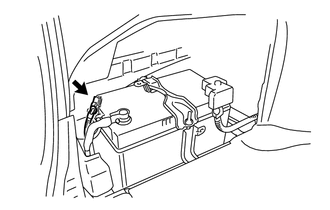
INSPECT BATTERY (BATTERY TEMPERATURE SENSOR)
-
Disconnect the battery (battery temperature sensor) connector.
-
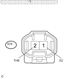
*1 Component without harness connected: (Battery Temperature Sensor) Measure the resistance according to the value(s) in the table below.
Standard resistance Tester Connection Condition Specified Condition S76-2 (THB) - S76-1 (E2) 0°C (32° F) 5.0 to 5.3 kΩ 20°C (68° F) 2.3 to 2.5 kΩ 40°C (104° F) 1.1 to 1.3 kΩ Tech Tips
The battery temperature sensor is not available separately. If it requires replacement, replace the auxiliary battery.
NG
REPLACE BATTERY
OK
-
-
CHECK HARNESS AND CONNECTOR (HYBRID VEHICLE CONTROL ECU - BATTERY TEMPERATURE SENSOR)
-
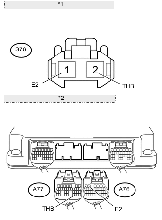
*1 Front view of wire harness connector: (to Battery Temperature Sensor) *2 Rear view of wire harness connector: (to Hybrid Vehicle Control ECU) Disconnect connectors A77 and A76 from the hybrid vehicle control ECU.
-
Measure the resistance according to the value(s) in the table below.
Standard resistance (Check for open) Tester Connection Switch Condition Specified Condition A77-30 (THB) - S76-2 (THB) Power switch off Below 1 Ω A76-5 (E2) - S76-1 (E2) Power switch off Below 1 Ω Standard resistance (Check for short) Tester Connection Switch Condition Specified Condition A77-30 (THB) or S76-2 (THB) - Body ground and other terminals Power switch off 10 kΩ or higher A76-5 (E2) or S76-1 (E2) - Body ground and other terminals Power switch off 10 kΩ or higher -
Turn the power switch on (IG).
-
Measure the voltage according to the value(s) in the table below.
Standard voltage Tester Connection Switch Condition Specified Condition A77-30 (THB) or S76-2 (THB) - Body ground Power switch on (IG) Below 1 V Note
Turning the power switch on (IG) with the hybrid vehicle control ECU connectors disconnected causes other DTCs to be stored. Clear the DTCs after performing this inspection.
OK
REPLACE HYBRID VEHICLE CONTROL ECU Click here
NG
REPAIR OR REPLACE HARNESS OR CONNECTOR
-