CRUISE CONTROL SYSTEM Cruise Control Switch Circuit
DESCRIPTION
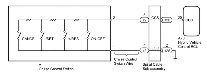
This circuit sends a signal to the hybrid vehicle control ECU depending on the cruise control main switch condition. The auxiliary battery supplies positive (+) auxiliary battery voltage to the circuit control switch. Then terminal CCS of the hybrid vehicle control ECU receives the voltage according to the switch condition.
WIRING DIAGRAM
PROCEDURE
-
READ VALUE USING INTELLIGENT TESTER (CRUISE CONTROL SWITCH)
-
Check the Data List for proper functioning of the cruise control switch Click here.
Cruise Control Tester Display Measurement Item/Range Normal Condition Diagnostic Note Main SW M-CPU Cruise control switch signal (Main CPU)/ON or OFF ON: Cruise control switch is ON
OFF: Cruise control switch is OFF
- Cancel Switch CANCEL switch signal/ON or OFF ON: CANCEL switch ON
OFF: CANCEL switch OFF
- SET/COAT Switch -/SET switch signal/ON or OFF ON: -/SET switch ON
OFF: -/SET switch OFF
- RES/ACC Switch +/RES switch signal/ON or OFF ON: +/RES switch ON
OFF: +/RES switch OFF
- OK When cruise control switch operation is performed, the results are the same as above.
OK 
PROCEED TO NEXT SUSPECTED AREA SHOWN IN PROBLEM SYMPTOMS TABLE Click here
NG 
-
-
INSPECT CRUISE CONTROL SWITCH WIRE
-
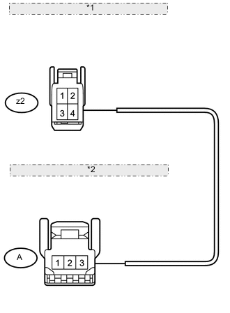
*1 Front view of wire harness connector: (to Spiral Cable Sub-assembly) *2 Front view of wire harness connector: (to Cruise Control Switch) Disconnect the z2 cable connector.
-
Disconnect the A switch connector.
-
Measure the resistance according to the value(s) in the table below.
Standard resistance Tester Connection Condition Specified Condition z2-3 - A-3 Always Below 1 Ω z2-4 - A-1 Always Below 1 Ω A-3 - Body ground Always 10 kΩ or higher A-1 - Body ground Always 10 kΩ or higher
NG
REPLACE CRUISE CONTROL SWITCH WIRE
OK
-
-
INSPECT CRUISE CONTROL SWITCH
-
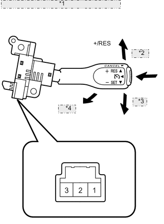
*1 Component without harness connected: (Cruise Control Switch) *2 ON-OFF *3 -/SET *4 CANCEL Remove the cruise control switch Click here.
-
Measure the resistance according to the value(s) in the table below.
Standard resistance Tester Connection Switch Condition Specified Condition 1 - 3 Cruise control switch ON Below 2.5 Ω 1 - 3 Cruise control switch OFF 1MΩ or higher 1 - 3 +/RES switch hold ON 235 to 245 Ω 1 - 3 -/SET switch hold ON 617 to 643 Ω 1 - 3 CANCEL switch hold ON 1509 to 1571 Ω
NG
REPLACE CRUISE CONTROL SWITCH Click here
OK
-
-
INSPECT SPIRAL CABLE SUB-ASSEMBLY
-
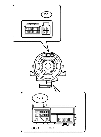
Disconnect the z2 switch connector.
-
Disconnect the L126 cable connector.
-
Measure the resistance according to the value(s) in the table below.
Standard resistance Tester Connection Condition Specified Condition z2-3 - L126-1 (CCS) Always Below 3 Ω z2-4 - L126-2 (ECC) Always Below 3 Ω z2-3 - Body ground Always 10 kΩ or higher z2-4 - Body ground Always 10 kΩ or higher
NG
REPLACE SPIRAL CABLE SUB-ASSEMBLY Click here
OK
-
-
CHECK HARNESS AND CONNECTOR (SPIRAL CABLE - HYBRID VEHICLE CONTROL ECU AND BODY GROUND)
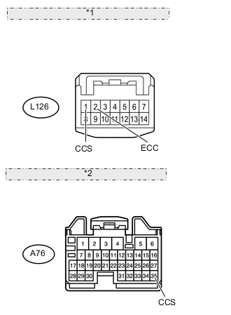
*1 Front view of wire harness connector: (to Spiral Cable Sub-assembly) *2 Front view of wire harness connector: (to Hybrid Vehicle Control ECU)
-
Disconnect the L126 cable connector.
-
Disconnect the A76 ECU connector.
-
Measure the resistance according to the value(s) in the table below.
Standard resistance Tester Connection Condition Specified Condition L126-1 (CCS) - A76-35 (CCS) Always Below 1 Ω L126-2 (ECC) - Body ground Always Below 1 Ω L126-1 (CCS) - Body ground Always 10 kΩ or higher
OK
REPLACE HYBRID VEHICLE CONTROL ECU Click here
NG
REPAIR OR REPLACE HARNESS OR CONNECTOR
-