ENTRY AND START SYSTEM, Diagnostic DTC:B2273
| DTC Code | DTC Name |
|---|---|
| B2273 | Ignition 2 Monitor Malfunction |
DESCRIPTION
This DTC is output when a malfunction occurs in the IG2D output circuit, which is between the ignition relay No. 2 (IG2) actuation circuit inside the main body ECU and the ignition relay No. 2 (IG2).
| DTC Code | Detection Condition | Trouble Area |
|---|---|---|
| B2273 | Ignition relay No. 2 (IG2) actuation circuit inside main body ECU or other related circuit is malfunctioning |
|
WIRING DIAGRAM
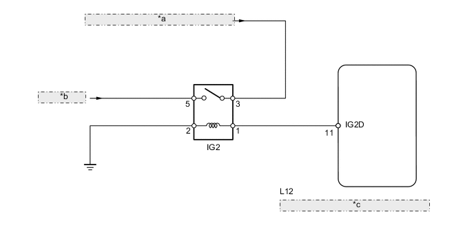
| *a | to Steering Lock Actuator Assembly (Steering Lock ECU) |
| *b | from Battery |
| *c | Main Body ECU (Driver Side Junction Block Assembly) |
PROCEDURE
-
READ VALUE USING INTELLIGENT TESTER (IG2 RELAY MONITOR (INSIDE))
-
Use the Data List to check if the ignition relay No. 2 (IG2) is functioning properly.
Main Body Tester Display Measurement Item/Range Normal Condition Diagnostic Note IG2 Relay Monitor (Inside) Ignition relay No. 2 (IG2) inner relay monitor/ON or OFF ON: Power switch ON (IG)
OFF: Power switch OFF
- OK When the power switch is turned ON (IG), ON is displayed on the tester.
NG 
INSPECT IGNITION RELAY NO. 2 (IG2) Click here
OK 
-
-
CHECK POWER SWITCH (SWITCH CONDITION)
-
Ensure the key is inside the cabin.
-
With the brake pedal released, check that the power source mode changes as shown below each time the power switch is pushed.
OK OFF → ON (ACC) → ON (IG) → OFF
OK 
USE SIMULATION METHOD TO CHECK Click here
NG
GO TO ENTRY AND START SYSTEM (POWER SOURCE MODE DOES NOT CHANGE) Click here
-
-
INSPECT IGNITION RELAY NO. 2 (IG2)
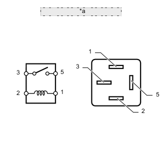
*a Ignition Relay No. 2 (IG2)
-
Remove the ignition relay No. 2 (IG2) from the engine room No. 2 junction block.
-
Measure the resistance according to the value(s) in the table below.
Standard resistance Tester Connection Condition Specified Condition 3 - 5 When battery voltage is applied to terminals 1 and 2 Below 1 Ω 3 - 5 When battery voltage is not applied to terminals 1 and 2 10 kΩ or higher
NG
REPLACE RELAY
OK
-
-
CHECK HARNESS AND CONNECTOR (MAIN BODY ECU - IGNITION RELAY NO. 2 (IG2))
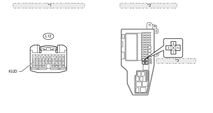
*1 Front view of wire harness connector: (to Main Body ECU) *2 Engine Room No. 2 Junction Block *3 Ignition Relay No. 2 (IG2)
-
Disconnect the L12 main body ECU connector.
-
Remove the ignition relay No. 2 (IG2) from the engine room No. 2 junction block.
-
Measure the resistance according to the value(s) in the table below.
Standard resistance Tester Connection Condition Specified Condition L12-11 (IG2D) - Ignition relay No. 2 (IG2) relay terminal 1 Always Below 1 Ω Ignition relay No. 2 (IG2) relay terminal 2 - Body ground Always Below 1 Ω L12-11 (IG2D) or ignition relay No. 2 (IG2) relay terminal 1 - Body ground Always 10 kΩ or higher
OK
REPLACE MAIN BODY ECU
NG
REPAIR OR REPLACE HARNESS OR CONNECTOR
-