IGNITION COIL AND SPARK PLUG INSTALLATION
CAUTION / NOTICE / HINT
Note
While the auxiliary battery is connected, even if the power switch is off, the brake control system activates when the brake pedal is depressed or the door courtesy switch turns on. Therefore during servicing of the brake system components, do not operate the brake pedal and open/close the doors while the auxiliary battery is connected.
PROCEDURE
-
INSTALL SPARK PLUG
-
Using a 16 mm plug wrench, install the 8 spark plugs.
- Torque:
- 21 N*m { 214 kgf*cm, 15 ft.*lbf }
-
-
INSTALL IGNITION COIL ASSEMBLY
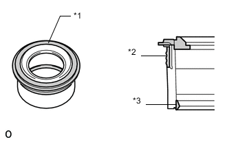
*1 Upper Surface *2 Outer Lip *3 Inner Lip
-
Visually check the spark plug tube gasket.
OK Inspection Area Specified Condition Upper surface No scratches or deformation Outer lip No scratches or deformation Inner lip No scratches If the result is not as specified, replace the spark plug tube gasket.
-
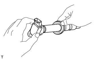
Slide the spark plug tube gasket onto the ignition coil assembly as shown in the illustration.
-
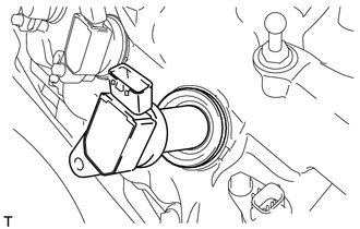
After installing the spark plug tube gasket, firmly insert the ignition coil assembly as shown in the illustration.
-
Install the 8 bolts.
- Torque:
- 10 N*m { 102 kgf*cm, 7 ft.*lbf }
-
Connect the 8 ignition coil assembly connectors.
-
-
INSTALL NO. 6 COVER SUB-ASSEMBLY
-
INSTALL ENGINE COVER SUB-ASSEMBLY LH
-
INSTALL NO. 5 COVER SUB-ASSEMBLY
-
INSTALL ENGINE COVER SUB-ASSEMBLY RH
-
INSTALL ENGINE OIL LEVEL DIPSTICK GUIDE
-
INSTALL SKID CONTROL ECU BRACKET (for RHD)
-
INSTALL SKID CONTROL ECU BRACKET (for LHD)
-
INSTALL INVERTER COOLING PIPE BRACKET (for RHD)
-
Attach the clamp of the frame wire and the clamp of the air conditioning harness to the inverter cooling pipe bracket.
-
Install the inverter cooling pipe bracket to the inverter with converter assembly with the bolt.
- Torque:
- 8.0 N*m { 82 kgf*cm, 71 in.*lbf }
-
Attach the clamp of the No. 2 inlet inverter cooling hose to the inverter cooling pipe bracket.
-
Attach the 2 clamps of the air conditioning harness to the No. 1 relay block.
-
-
CONNECT FRAME WIRE
-
Attach the 2 claws of the frame wire to the No. 1 relay block.
-
Install the frame wire to the No. 1 relay block with the 2 nuts.
- Torque:
- 13 N*m { 130 kgf*cm, 10 ft.*lbf }
-
Install the No. 1 relay block cover.
-
-
CONNECT INLET INVERTER COOLING PIPE (for LHD)
-
Install the inlet inverter cooling pipe with the 2 bolts.
- Torque:
- 13 N*m { 127 kgf*cm, 9 ft.*lbf }
-
-
CONNECT GENERATOR CABLE (for RHD)
-
CONNECT GENERATOR CABLE (for LHD)
-
CONNECT MOTOR CABLE (for RHD)
-
CONNECT MOTOR CABLE (for LHD)
-
INSTALL INVERTER TERMINAL COVER (for RHD)
-
INSTALL INVERTER TERMINAL COVER (for LHD)
-
INSTALL INVERTER COVER ASSEMBLY LH (for RHD)
-
INSTALL INVERTER COVER ASSEMBLY RH (for LHD)
-
INSTALL MOTOR CABLE COVER LH (for RHD)
-
INSTALL MOTOR CABLE COVER RH (for LHD)
-
INSTALL COWL TOP VENTILATOR LOUVER LH (for RHD)
-
INSTALL COWL TOP VENTILATOR LOUVER RH (for LHD)
-
INSTALL AIR CLEANER ASSEMBLY RH
-
INSTALL AIR CLEANER ASSEMBLY LH
-
INSTALL INTAKE AIR CONNECTOR PIPE
-
INSTALL NO. 1 AIR CLEANER INLET
-
INSTALL SERVICE PLUG GRIP
-
CONNECT CABLE TO NEGATIVE AUXILIARY BATTERY TERMINAL
Note
When disconnecting the cable, some systems need to be initialized after the cable is reconnected Click here.
-
INSTALL BATTERY SERVICE HOLE COVER LH
-
INSTALL DECK TRIM SIDE BOARD LH (w/o Spare Tire)
-
INSTALL DECK BOARD ASSEMBLY (w/o Spare Tire)
-
INSTALL LUGGAGE COMPARTMENT MAT SUB-ASSEMBLY (w/ Spare Tire)
-
INSTALL ENGINE ROOM SIDE COVER LH
-
Install the engine room side cover LH with the 5 clips.
-
-
INSTALL ENGINE ROOM SIDE COVER RH
-
Install the engine room side cover RH with the 5 clips.
-
-
INSTALL AIR CLEANER INLET COVER SUB-ASSEMBLY
-
INSTALL V-BANK COVER SUB-ASSEMBLY