IGNITION COIL AND SPARK PLUG REMOVAL
CAUTION / NOTICE / HINT
Note
While the auxiliary battery is connected, even if the power switch is off, the brake control system activates when the brake pedal is depressed or the door courtesy switch turns on. Therefore during servicing of the brake system components, do not operate the brake pedal and open/close the doors while the auxiliary battery is connected.
PROCEDURE
-
REMOVE LUGGAGE COMPARTMENT MAT SUB-ASSEMBLY (w/ Spare Tire)
-
REMOVE DECK BOARD ASSEMBLY (w/o Spare Tire)
-
REMOVE DECK TRIM SIDE BOARD LH (w/o Spare Tire)
-
REMOVE BATTERY SERVICE HOLE COVER LH
-
PRECAUTION
Note
After turning the power switch off, waiting time may be required before disconnecting the cable from the auxiliary battery terminal. Therefore, make sure to read the disconnecting the cable from the auxiliary battery terminal notice before proceeding with work Click here.
-
DISCONNECT CABLE FROM NEGATIVE AUXILIARY BATTERY TERMINAL
Note
When disconnecting the cable, some systems need to be initialized after the cable is reconnected Click here.
-
REMOVE SERVICE PLUG GRIP
-
REMOVE V-BANK COVER SUB-ASSEMBLY
-
REMOVE AIR CLEANER INLET COVER SUB-ASSEMBLY
-
REMOVE ENGINE ROOM SIDE COVER RH
-
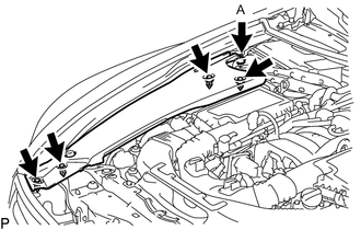
for LHD:
Remove the 5 clips and engine room side cover RH.
Note
Remove the clip labeled A by turning it to prevent the engine room side cover RH and bracket from being damaged.
Tech Tips
The clip labeled A cannot be removed from the engine room side cover RH.
-
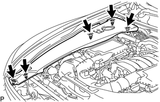
for RHD:
Remove the 5 clips and engine room side cover RH.
-
-
REMOVE ENGINE ROOM SIDE COVER LH
-
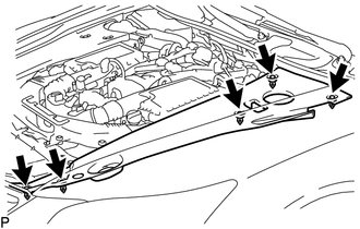
for LHD:
Remove the 5 clips and engine room side cover LH.
-
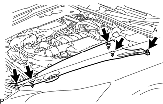
for RHD:
Remove the 5 clips and engine room side cover LH.
Note
Remove the clip labeled A by turning it to prevent the engine room side cover LH and bracket from being damaged.
Tech Tips
The clip labeled A cannot be removed from the engine room side cover LH.
-
-
REMOVE NO. 1 AIR CLEANER INLET
-
REMOVE INTAKE AIR CONNECTOR PIPE
-
REMOVE AIR CLEANER ASSEMBLY LH
-
REMOVE AIR CLEANER ASSEMBLY RH
-
REMOVE COWL TOP VENTILATOR LOUVER RH (for LHD)
-
REMOVE COWL TOP VENTILATOR LOUVER LH (for RHD)
-
REMOVE MOTOR CABLE COVER RH (for LHD)
-
REMOVE MOTOR CABLE COVER LH (for RHD)
-
REMOVE INVERTER COVER ASSEMBLY RH (for LHD)
-
REMOVE INVERTER COVER ASSEMBLY LH (for RHD)
-
REMOVE CONNECTOR COVER ASSEMBLY (for LHD)
-
REMOVE CONNECTOR COVER ASSEMBLY (for RHD)
-
CHECK TERMINAL VOLTAGE (for LHD)
-
CHECK TERMINAL VOLTAGE (for RHD)
-
INSTALL CONNECTOR COVER ASSEMBLY (for LHD)
-
INSTALL CONNECTOR COVER ASSEMBLY (for RHD)
-
REMOVE INVERTER TERMINAL COVER (for LHD)
-
REMOVE INVERTER TERMINAL COVER (for RHD)
-
DISCONNECT MOTOR CABLE (for LHD)
-
DISCONNECT MOTOR CABLE (for RHD)
-
DISCONNECT GENERATOR CABLE (for LHD)
-
DISCONNECT GENERATOR CABLE (for RHD)
-
DISCONNECT INLET INVERTER COOLING PIPE (for LHD)
-
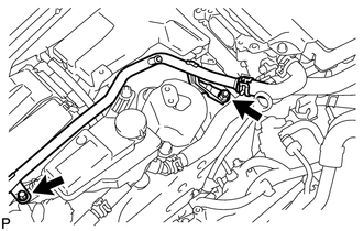
Remove the 2 bolts and disconnect the inlet inverter cooling pipe.
-
-
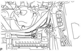
DISCONNECT FRAME WIRE
-
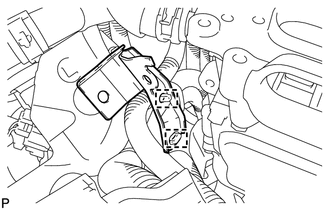
Remove the No. 1 relay block cover.
-
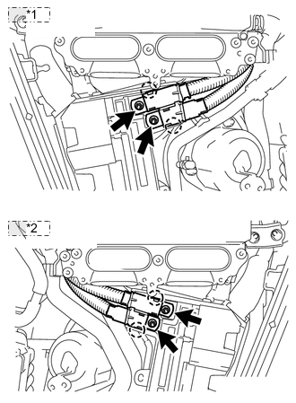
*1 for LHD: *2 for RHD: Remove the 2 nuts from the No. 1 relay block.
-
Detach the 2 claws to disconnect the frame wire from the No. 1 relay block.
-
-
REMOVE INVERTER COOLING PIPE BRACKET (for RHD)
-
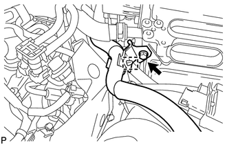
Detach the 2 clamps to disconnect the air conditioning harness from the No. 1 relay block.
-
Detach the clamp of the No. 2 inlet inverter cooling hose from the inverter cooling pipe bracket.
-
Remove the bolt, and then remove the inverter cooling pipe bracket from the inverter with converter assembly.
-
Detach the clamp of the frame wire and the clamp of the air conditioning harness. Then remove the inverter cooling pipe bracket.
-
-
REMOVE SKID CONTROL ECU BRACKET (for LHD)
-
REMOVE SKID CONTROL ECU BRACKET (for RHD)
-
REMOVE ENGINE OIL LEVEL DIPSTICK GUIDE
-
REMOVE ENGINE COVER SUB-ASSEMBLY RH
-
REMOVE NO. 5 COVER SUB-ASSEMBLY
-
REMOVE ENGINE COVER SUB-ASSEMBLY LH
-
REMOVE NO. 6 COVER SUB-ASSEMBLY
-
REMOVE IGNITION COIL ASSEMBLY
-
Disconnect the 8 ignition coil assembly connectors.
-
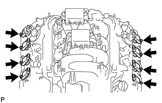
Remove the 8 bolts.
-
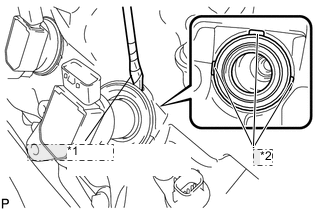
*1 Protective Tape *2 Cutout Using a screwdriver, pry at the cutouts to remove the 8 ignition coil assemblies together with the 8 spark plug tube gaskets.
Note
Do not damage the cylinder head cover when removing the spark plug tube gasket.
Tech Tips
Tape the screwdriver tip before use.
-
-
REMOVE SPARK PLUG
-
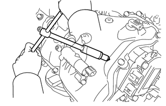
Using a 16 mm plug wrench, remove the 8 spark plugs.
-