OIL PUMP INSTALLATION

CAUTION / NOTICE / HINT
Tech Tips
When viewed from the rear of the engine assembly, Bank 1 is on the left side and Bank 2 is on the right side.
PROCEDURE
-
INSTALL WATER INLET PIPE
-
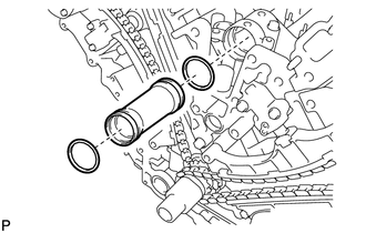
Apply soapy water to 2 new O-rings and install them to the inlet pipe.
-
Install the inlet pipe to the No. 1 heat exchanger cover.
-
-
INSTALL TIMING CHAIN COVER SUB-ASSEMBLY
-
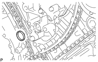
Install a new oil pump gasket.
-
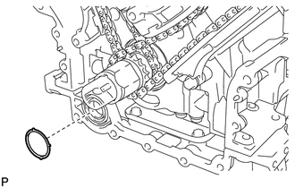
Install a new O-ring.
-
Apply seal packing in a continuous line to the timing chain cover as shown in the following illustration.
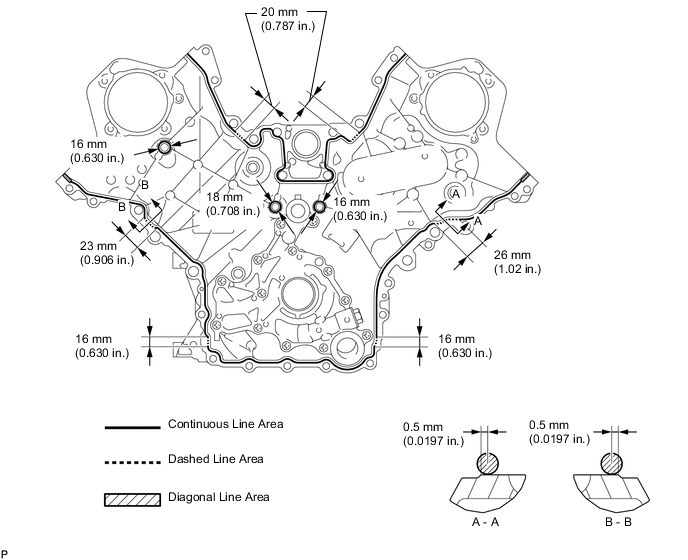
Seal packing Toyota Genuine Seal Packing Black, Three Bond 1207B or equivalent
-
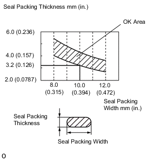
Apply Seal Packing as Follows Area Seal Packing Diameter Application position from inside edge of cover Continuous Line Area 3.0 to 4.0 mm (0.118 to 0.157 in.) 2.5 mm (0.0984 in.) Dashed Line Area 6.4 mm (0.252 in.) or more, or within OK area shown in illustration 0.5 mm (0.0197 in.) Diagonal Line Area 3.0 to 4.0 mm (0.118 to 0.157 in.) 5.5 mm (0.217 in.)
Note
-
When the contact surfaces are wet, wipe them with an oil-free cloth before applying seal packing.
-
Install the chain cover within 3 minutes and tighten the bolts within 10 minutes after applying seal packing.
-
Do not start the engine for at least 2 hours after installation.
-
-
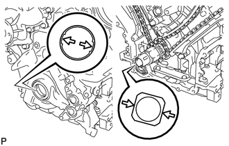
Align the drive rotor spline of the oil pump and the crankshaft as shown in the illustration. Install the spline and chain cover to the crankshaft.
-
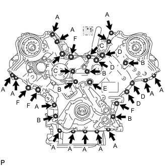
*1 Nut Temporarily install the timing chain cover with the 30 bolts and nut.
Bolt Length Item Length Thread Diameter Bolt A 25 mm (0.984 in.) 8 mm (0.315 in.) Bolt B 55 mm (2.17 in.) 8 mm (0.315 in.) Bolt C 70 mm (2.76 in.) 8 mm (0.315 in.) Bolt D 35 mm (1.38 in.) 10 mm (0.394 in.) Bolt E 55 mm (2.17 in.) 10 mm (0.394 in.) Bolt F 80 mm (3.15 in.) 10 mm (0.394 in.) Note
Make sure that there is no oil on the bolt threads.
-
Tighten the bolt.
- Torque:
- 23 N*m { 235 kgf*cm, 17 ft.*lbf }
-
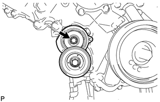
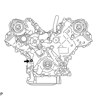
Install the belt tensioner with the bolt.
- Torque:
- 23 N*m { 235 kgf*cm, 17 ft.*lbf }
-
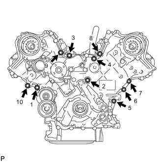
Tighten the 10 bolts in several steps, in the sequence shown in the illustration.
- Torque:
- 47 N*m { 479 kgf*cm, 35 ft.*lbf }
-
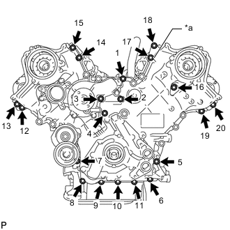
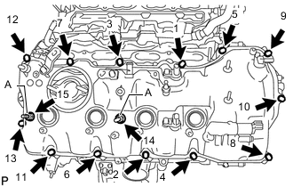
*a Nut Tighten the 19 bolts and nut in several steps, in the sequence shown in the illustration.
- Torque:
- 23 N*m { 235 kgf*cm, 17 ft.*lbf }
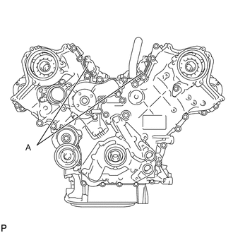
Note
After the installation, if the seal packing has seeped out at the areas labeled A shown in the illustration, wipe it off.
-
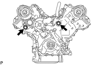
Install 2 new gaskets and the 2 plugs.
- Torque:
- 46 N*m { 469 kgf*cm, 34 ft.*lbf }
-
-
INSTALL CYLINDER HEAD COVER SUB-ASSEMBLY LH
-
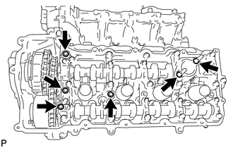
Install 4 new gaskets and 2 new O-rings to the camshaft bearing caps (No. 2, No. 3 and No. 7).
-
Install a new gasket to the cylinder head cover.
Note
Remove any oil from the contact surface.
-
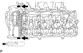
*1 Seal packing Apply seal packing as shown the illustration.
Seal packing Toyota Genuine Seal Packing Black, Three Bond 1207B or equivalent Standard seal diameter 2.0 to 3.0 mm (0.0787 to 0.118 in.) Note
-
Remove any oil from the contact surface.
-
Install the cylinder head cover within 3 minutes and tighten the bolts within 15 minutes after applying seal packing.
-
Do not start the engine for at least 2 hours after the installation.
-
-
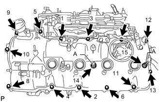
Install the cylinder head cover and 2 new seal washers with the 15 bolts in the order shown in the illustration.
- Torque:
- for bolt A
- 21 N*m { 214 kgf*cm, 15 ft.*lbf }
- except bolt A
- 12 N*m { 122 kgf*cm, 9 ft.*lbf }
-
Install the fuel pump spacer.
-
-
INSTALL CYLINDER HEAD COVER SUB-ASSEMBLY RH
-
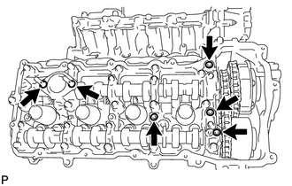
Install 4 new gaskets and 2 new O-rings to the camshaft bearing caps (No. 1, No. 3 and No. 6).
-
Install a new gasket to the cylinder head cover.
Note
Remove any oil from the contact surface.
-
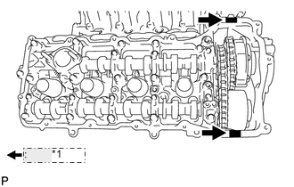
*1 Seal packing Apply seal packing as shown the illustration.
Seal packing Toyota Genuine Seal Packing Black, Three Bond 1207B or equivalent Standard seal diameter 2.0 to 3.0 mm (0.0787 to 0.118 in.) Note
-
Remove any oil from the contact surface.
-
Install the cylinder head cover within 3 minutes and tighten the bolts within 15 minutes after applying seal packing.
-
Do not start the engine for at least 2 hours after the installation.
-
-
Install the cylinder head cover and 2 new seal washers with the 15 bolts in the order shown in the illustration.
- Torque:
- for bolt A
- 21 N*m { 214 kgf*cm, 15 ft.*lbf }
- except bolt A
- 12 N*m { 122 kgf*cm, 9 ft.*lbf }
-
Install the fuel pump spacer.
-
-
INSTALL FRONT CRANKSHAFT OIL SEAL
-
INSTALL CRANKSHAFT TIMING GEAR KEY
-
INSTALL IGNITION COIL ASSEMBLY
-
INSTALL CRANKSHAFT PULLEY
-
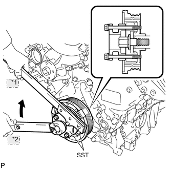
*1 Hold *2 Turn Align the pulley set key with the key groove of the pulley, and slide on the pulley.
-
Using SST, install the pulley bolt.
- SST
- 09213-54015 ( 90119-08216 )
- 09330-00021
- Torque:
- 300 N*m { 3059 kgf*cm, 221 ft.*lbf }
-
-
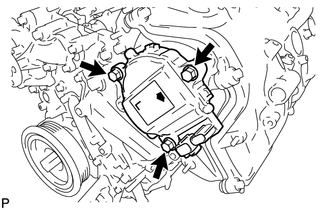
INSTALL OIL FILTER BRACKET
-
Install 2 new gaskets and the filter bracket with the 3 bolts.
- Torque:
- 21 N*m { 214 kgf*cm, 15 ft.*lbf }
-
-
INSTALL OIL FILTER ELEMENT
-
INSTALL CAMSHAFT TIMING CONTROL MOTOR ASSEMBLY RH
-
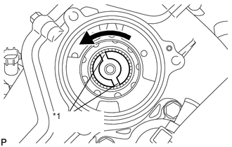
*1 Index Slot Turn the camshaft timing gear assembly's intermediate shaft index slot in the counterclockwise direction by hand, and set it to the maximum retard angle position.
Tech Tips
-
When the cam of the camshaft lifts the valve, the intermediate shaft becomes difficult to turn.
-
The position where the intermediate shaft stops is the maximum retard angle.
-
-
Install a new O-ring to the timing chain cover.
-
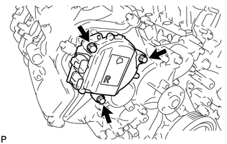
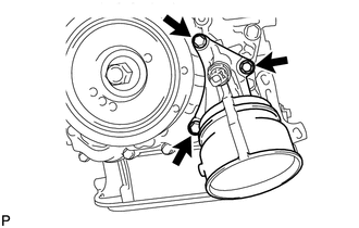
Align the joint of the camshaft timing control motor and the keyway of the camshaft timing gear assembly, and install the motor with the 3 bolts.
- Torque:
- 21 N*m { 214 kgf*cm, 15 ft.*lbf }
Note
-
Check that [R] is printed on the label of the camshaft timing control motor.
-
Do not allow foreign matter to contact the oil seal face of the camshaft timing control motor (connecting surface with timing chain cover sub-assembly).
-
When installing the camshaft timing control motor, do not use excessive force.
-
Align the timing chain cover sub-assembly knock pin with the camshaft timing control motor pin hole to install the camshaft timing control motor.
-
Install the camshaft timing control motor with the arrow facing upward, as shown in the illustration.
-
Do not drop the camshaft timing control motor. If dropped, replace it.
-
Do not disassemble the camshaft timing control motor assembly. If disassembled, replace it.
-
-
INSTALL CAMSHAFT TIMING CONTROL MOTOR ASSEMBLY LH
-
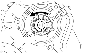
*1 Index Slot Turn the camshaft timing gear assembly's intermediate shaft index slot in the counterclockwise direction by hand, and set it to the maximum retard angle position.
Tech Tips
-
When the cam of the camshaft lifts the valve, the intermediate shaft becomes difficult to turn.
-
The position where the intermediate shaft stops is the maximum retard angle.
-
-
Install a new O-ring to the timing chain cover.
-
Align the joint of the camshaft timing control motor and the keyway of the camshaft timing gear assembly, and install the motor with the 3 bolts.
- Torque:
- 21 N*m { 214 kgf*cm, 15 ft.*lbf }
Note
-
Check that [L] is printed on the label of the camshaft timing control motor.
-
Do not allow foreign matter to contact the oil seal face of the camshaft timing control motor (connecting surface with timing chain cover sub-assembly).
-
When installing the camshaft timing control motor, do not use excessive force.
-
Align the timing chain cover sub-assembly knock pin with the camshaft timing control motor pin hole to install the camshaft timing control motor.
-
Install the camshaft timing control motor with the arrow facing upward, as shown in the illustration.
-
Do not drop the camshaft timing control motor. If dropped, replace it.
-
Do not disassemble the camshaft timing control motor assembly. If disassembled, replace it.
-
-
INSTALL FRONT WATER BY-PASS JOINT
-
INSTALL WATER PUMP PULLEY
-
INSTALL WATER INLET HOUSING
-
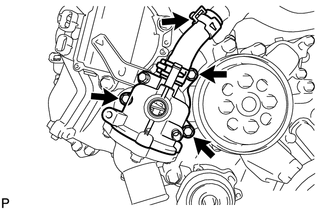
Install a new gasket and the inlet housing with the 3 bolts.
- Torque:
- 21 N*m { 214 kgf*cm, 15 ft.*lbf }
-
Using needle-nose pliers, grip the claws of the clip and slide the clip to connect the water inlet hose.
-
-
INSTALL FUEL PUMP ASSEMBLY (for Bank 2)
-
INSTALL FUEL PUMP ASSEMBLY (for Bank 1)
-
INSTALL NO. 3 FUEL PIPE SUB-ASSEMBLY
-
INSTALL NO. 2 FUEL PIPE SUB-ASSEMBLY
-
INSTALL FUEL PRESSURE PULSATION DAMPER ASSEMBLY
-
INSTALL INTAKE MANIFOLD ASSEMBLY
-
INSTALL WATER BY-PASS PIPE SUB-ASSEMBLY
-
INSTALL HEATER WATER PUMP ASSEMBLY
-
INSTALL PURGE VSV
-
INSTALL NO. 1 ENGINE COVER
-
INSTALL INJECTOR DRIVER
-
INSTALL ENGINE WIRE
-
INSTALL NO. 5 COVER SUB-ASSEMBLY
-
INSTALL ENGINE COVER SUB-ASSEMBLY RH
-
INSTALL NO. 6 COVER SUB-ASSEMBLY
-
INSTALL ENGINE COVER SUB-ASSEMBLY LH
-
INSTALL WITH MOTOR COMPRESSOR ASSEMBLY
-
INSTALL V-RIBBED BELT
-
INSTALL ENGINE ASSEMBLY