OIL PUMP REMOVAL

CAUTION / NOTICE / HINT
Tech Tips
When viewed from the rear of the engine assembly, Bank 1 is on the left side and Bank 2 is on the right side.
PROCEDURE
-
REMOVE ENGINE ASSEMBLY
-
REMOVE V-RIBBED BELT
-
REMOVE WITH MOTOR COMPRESSOR ASSEMBLY
-
REMOVE ENGINE COVER SUB-ASSEMBLY LH
-
REMOVE NO. 6 COVER SUB-ASSEMBLY
-
REMOVE ENGINE COVER SUB-ASSEMBLY RH
-
REMOVE NO. 5 COVER SUB-ASSEMBLY
-
REMOVE ENGINE WIRE
-
REMOVE INJECTOR DRIVER
-
REMOVE NO. 1 ENGINE COVER
-
REMOVE PURGE VSV
-
REMOVE HEATER WATER PUMP ASSEMBLY
-
REMOVE WATER BY-PASS PIPE SUB-ASSEMBLY
-
REMOVE INTAKE MANIFOLD ASSEMBLY
-
REMOVE FUEL PRESSURE PULSATION DAMPER ASSEMBLY
-
REMOVE NO. 3 FUEL PIPE SUB-ASSEMBLY
-
REMOVE NO. 2 FUEL PIPE SUB-ASSEMBLY
-
REMOVE FUEL PUMP ASSEMBLY (for Bank 1)
-
REMOVE FUEL PUMP ASSEMBLY (for Bank 2)
-
REMOVE WATER INLET HOUSING
-
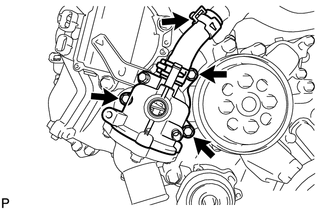
Using needle-nose pliers, grip the claws of the clip and slide the clip to disconnect the water inlet hose.
-
Remove the 3 bolts, water inlet housing and gasket.
-
-
REMOVE WATER PUMP PULLEY
-
REMOVE V-RIBBED BELT TENSIONER ASSEMBLY
-
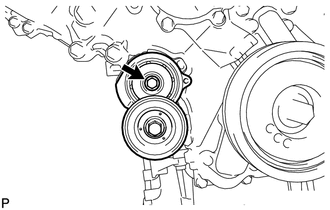
Remove the bolt and belt tensioner.
-
-
REMOVE FRONT WATER BY-PASS JOINT
-
REMOVE CAMSHAFT TIMING CONTROL MOTOR ASSEMBLY LH
-
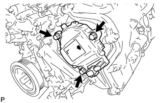
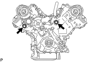
Remove the 3 bolts and camshaft timing control motor.
-
Remove the O-ring from the timing chain cover.
-
-
REMOVE CAMSHAFT TIMING CONTROL MOTOR ASSEMBLY RH
-
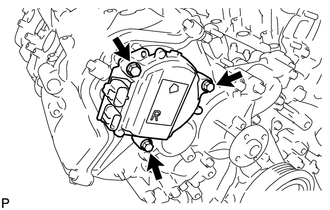
Remove the 3 bolts and camshaft timing control motor.
-
Remove the O-ring from the timing chain cover.
-
-
REMOVE OIL FILTER ELEMENT
-
REMOVE OIL FILTER BRACKET
-
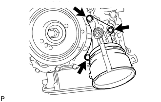
Remove the 3 bolts, filter bracket and 2 gaskets.
-
-
REMOVE CRANKSHAFT PULLEY
-
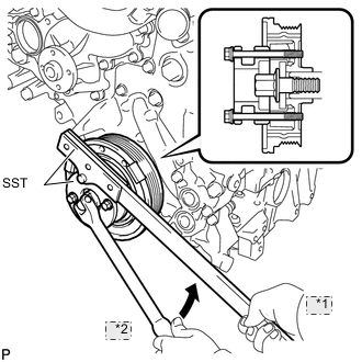
*1 Hold *2 Turn Using SST, loosen the crankshaft pulley set bolt until 2 or 3 threads are engaged.
- SST
- 09213-54015 ( 90119-08216 )
- 09330-00021
-
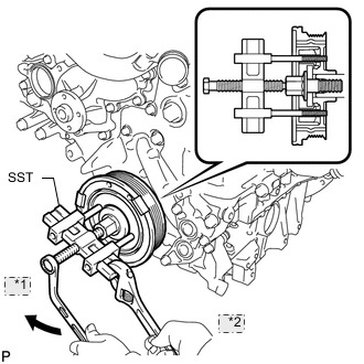
*1 Turn *2 Hold Using the pulley set bolt and SST, remove the crankshaft pulley.
- SST
- 09950-50013 ( 09951-05010, 09952-05010, 09953-05010, 09954-05031 )
-
-
REMOVE CRANKSHAFT TIMING GEAR KEY
-
REMOVE IGNITION COIL ASSEMBLY
-
REMOVE CYLINDER HEAD COVER SUB-ASSEMBLY LH
-
Remove the fuel pump spacer.
-
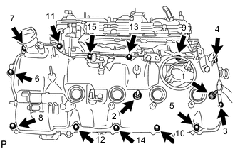
Remove the 15 bolts in the order shown in the illustration. Then remove the 2 seal washers, cylinder head cover and gasket.
Tech Tips
Make sure the removed parts are returned to the same places they were removed from.
-
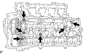
Remove the 4 gaskets and 2 O-rings from the camshaft bearing caps (No. 2, No. 3 and No. 7).
-
-
REMOVE CYLINDER HEAD COVER SUB-ASSEMBLY RH
-
Remove the fuel pump spacer.
-
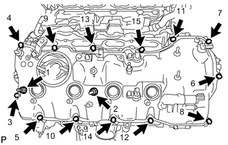
Remove the 15 bolts in the order shown in the illustration. Then remove the 2 seal washers, cylinder head cover and gasket.
Tech Tips
Make sure the removed parts are returned to the same places they were removed from.
-
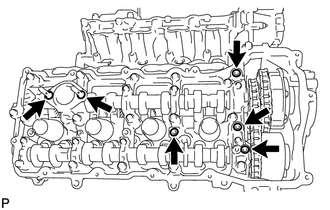
Remove the 4 gaskets and 2 O-rings from the camshaft bearing caps (No. 1, No. 3 and No. 6).
-
-
REMOVE TIMING CHAIN COVER SUB-ASSEMBLY
-
Remove the 2 plugs and 2 gaskets.
-
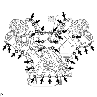
*1 Nut Remove the 30 bolts and nut shown in the illustration.
-
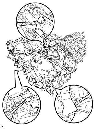
Remove the timing chain cover by prying between the timing chain cover and cylinder head or cylinder block with a screwdriver as shown in the illustration.
Note
Be careful not to damage the contact surfaces of the cylinder head, cylinder block and chain cover.
Tech Tips
Tape the screwdriver tip before use.
-
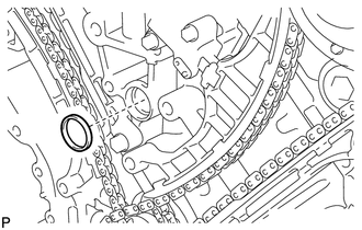
Remove the oil pump gasket from the cylinder block.
-
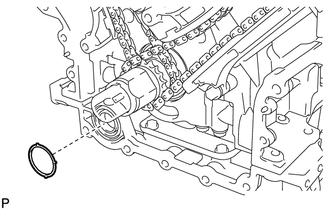
Remove the O-ring from the oil pan.
-
-
REMOVE WATER INLET PIPE
-
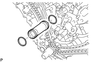
Remove the water inlet pipe.
-
Remove the 2 O-rings from the water inlet pipe.
-
-
REMOVE FRONT CRANKSHAFT OIL SEAL