RADIATOR INSTALLATION
PROCEDURE
-
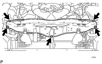
INSTALL LOWER RADIATOR SUPPORT
-
Install the 2 lower radiator supports.
-
-
INSTALL RADIATOR SUPPORT CUSHION
-
Install the 2 radiator support cushions.
-
-
INSTALL COOLER CONDENSER ASSEMBLY
-
INSTALL FAN SHROUD WITH FAN AND MOTOR
-
INSTALL RADIATOR ASSEMBLY
-
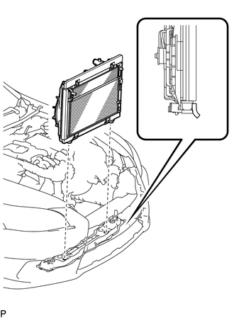
Install the radiator assembly to the front crossmember.
Note
Do not allow the radiator assembly to interfere with other parts.
Tech Tips
Install the radiator assembly to the front side holes of the lower support of the radiator assembly.
-
-
CONNECT LIQUID TUBE SUB-ASSEMBLY A
-
Remove the attached vinyl tape from the pipe and the connecting part of the cooler condenser.
-
Sufficiently apply compressor oil to a new O-ring and the fitting surface of the pipe joint.
Compressor oil ND-OIL 11 or equivalent -
Install the O-ring to the liquid tube.
-
Install the liquid tube to the cooler condenser with the 2 bolts.
- Torque:
- 5.4 N*m { 55 kgf*cm, 48 in.*lbf }
Note
-
When tightening the bolt, do not allow any tools to contact the pipe.
-
When tightening the bolt, hold a part of the pipe near the connector.
-
-
CONNECT DISCHARGE HOSE SUB-ASSEMBLY
-
Remove the attached vinyl tape from the discharge hose sub-assembly and the connecting part of the cooler condenser.
-
Sufficiently apply compressor oil to a new O-ring and the fitting surface of the hose joint.
Compressor oil ND-OIL 11 or equivalent -
Install the O-ring to the discharge hose sub-assembly.
-
Install the discharge hose sub-assembly to the cooler condenser with the bolt.
- Torque:
- 5.4 N*m { 55 kgf*cm, 48 in.*lbf }
Note
-
When tightening the bolt, do not allow any tools to contact the pipe.
-
When tightening the bolt, hold a part of the pipe near the connector.
-
-
CONNECT NO. 1 INVERTER COOLING HOSE
-
Connect the No. 1 inverter cooling hose and install the clip.
-
-
CONNECT NO. 2 INVERTER COOLING HOSE
-
Connect the No. 2 inverter cooling hose and install the clip.
-
-
INSTALL HOOD LOCK ASSEMBLY
-
Install the hood lock assembly to the hood lock control cable.
-
-
INSTALL HOOD LOCK CONTROL CABLE COVER
-
Connect the wire harness clamp to the hood lock control cable cover.
-
Connect the hood lock control cable to the hood lock control cable cover.
-
Attach the guide to install the hood lock control cable cover.
-
-
INSTALL RADIATOR UPPER SUPPORT SUB-ASSEMBLY
-
Connect the 3 connectors and 5 wire harness clamps to connect the wire harness.
-
Install the radiator upper support sub-assembly with the 5 bolts.
- Torque:
- 8.0 N*m { 82 kgf*cm, 71 in.*lbf }
-
-
CONNECT WIRE HARNESS
-
Attach the 8 wire harness clamps to fan shroud and connect the 3 connectors.
-
-
CONNECT HOOD LOCK ASSEMBLY
-
Connect the connector.
-
Connect the hood lock assembly with the 2 bolts and lock nut.
- Torque:
- 8.0 N*m { 82 kgf*cm, 71 in.*lbf }
-
Install the lock nut cap.
-
-
CONNECT HOOD LOCK CONTROL CABLE COVER
-
Connect the hood lock control cable cover with the 3 screws and attach the claw.
-
-
INSTALL MILLIMETER WAVE RADAR SENSOR ASSEMBLY (w/ Dynamic Radar Cruise Control System)
-
INSTALL OUTLET ENGINE ROOM ECU DUCT
-
CONNECT NO. 2 OIL COOLER OUTLET HOSE
-
Connect the No. 2 oil cooler outlet hose to the radiator assembly.
-
-
CONNECT NO. 2 OIL COOLER INLET HOSE
-
Connect the No. 2 oil cooler inlet hose to the radiator assembly.
-
-
INSTALL NO. 2 RADIATOR HOSE
-
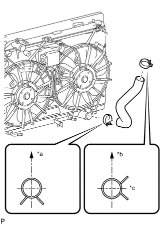
Text in Illustration *a Upper *b Front Side of Vehicle *c RH Side Install the No. 2 radiator hose.
Tech Tips
The direction of each hose clamp is indicated in the illustration.
-
-
INSTALL NO. 1 RADIATOR HOSE
-
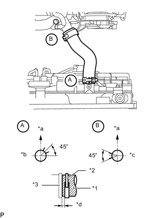
Text in Illustration *1 No. 1 Radiator Hose *2 Hose Clamp *3 Stopper *a Upper *b RH Side *c LH Side *d 1.0 to 5.0 mm (0.0393 to 0.197 in.) Install the No. 1 radiator hose to the radiator and water outlet, and then secure it with the hose clamps.
Tech Tips
-
The direction of each hose clamp is indicated in the illustration.
-
Insert the No. 2 radiator hose into the stopper. Set each hose clamp so that the clearance between the hose clamp and the stopper is within 1.0 to 5.0 mm (0.0393 to 0.197 in.).
-
-
-
INSTALL RADIATOR RESERVOIR ASSEMBLY
-
ADD COOLANT (for Inverter)
-
ADD ENGINE COOLANT
-
CHARGE REFRIGERANT
-
CHECK TRANSMISSION FLUID LEVEL
-
INSPECT FOR COOLANT LEAK (for Inverter)
-
INSPECT FOR COOLANT LEAK
-
INSPECT FOR REFRIGERANT LEAK
-
ADJUST MILLIMETER WAVE RADAR SENSOR ASSEMBLY (w/ Dynamic Radar Cruise Control System)
-
INSTALL FRONT CENTER FLOOR COVER (w/ Cover)
-
INSTALL NO. 1 ENGINE UNDER COVER
-
INSTALL NO. 1 AIR CLEANER INLET
-
INSTALL V-BANK COVER SUB-ASSEMBLY
-
INSTALL FRONT BUMPER REINFORCEMENT