WATER PUMP INSTALLATION

PROCEDURE
-
INSTALL ENGINE WATER PUMP ASSEMBLY
-
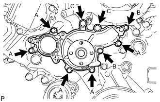
Install the engine water pump and a new gasket with the 9 bolts as shown in the illustration.
- Torque:
- for bolt A
- 20 N*m { 204 kgf*cm, 15 ft.*lbf }
- for bolt B
- 23 N*m { 235 kgf*cm, 17 ft.*lbf }
- for bolt C
- 47 N*m { 479 kgf*cm, 35 ft.*lbf }
-
-
INSTALL WATER PUMP PULLEY
-
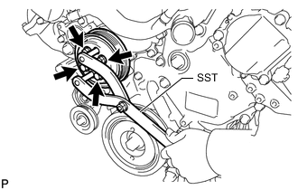
Temporarily install the pulley with the 4 bolts.
-
Using SST, hold the pulley and tighten the 4 bolts.
- SST
- 09960-10010 ( 09962-01000, 09963-01000 )
- Torque:
- 21 N*m { 214 kgf*cm, 15 ft.*lbf }
-
-
INSTALL WATER INLET HOUSING
-
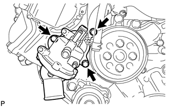
Install a new gasket to the engine water pump.
-
Install the water inlet housing with the 3 bolts.
- Torque:
- 21 N*m { 214 kgf*cm, 15 ft.*lbf }
-
-
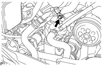
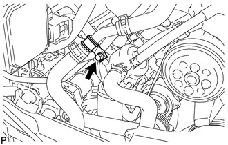
CONNECT INLET HEATER WATER HOSE
-
Using needle-nose pliers, grip the claws of the hose clamp and slide the hose clamp to connect the inlet heater water hose.
-
-
CONNECT WATER INLET HOSE
-
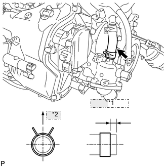
*1 1.0 to 5.0 mm *2 Upper Using needle-nose pliers, grip the claws of the hose clamp and slide the hose clamp to connect the water inlet hose.
Tech Tips
-
The direction of the hose clamp is indicated in the illustration.
-
Insert the hose into the stopper. Set the hose clamp so that the clearance between the hose clamp and stopper is within 1.0 to 5.0 mm (0.0398 to 0.197 in.).
-
-
-
CONNECT NO. 5 WATER BY-PASS HOSE
-
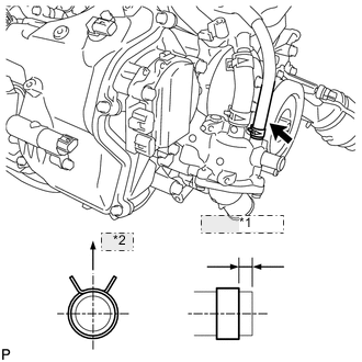
*1 1.0 to 5.0 mm *2 Upper Using needle-nose pliers, grip the claws of the clip and slide the clip to connect the No. 5 water by-pass hose.
Tech Tips
-
The direction of the hose clamp is indicated in the illustration.
-
Insert the hose into the stopper. Set the hose clamp so that the clearance between the hose clamp and stopper is within 1.0 to 5.0 mm (0.0398 to 0.197 in.).
-
-
-
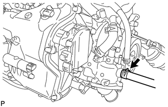
CONNECT WIRE HARNESS
-
Connect the wire harness with the bolt.
- Torque:
- 10 N*m { 102 kgf*cm, 7 ft.*lbf }
-
-
CONNECT WATER HOSE SUB-ASSEMBLY
-
Connect the water hose with the bolt.
- Torque:
- 10 N*m { 102 kgf*cm, 7 ft.*lbf }
-
-
CONNECT NO. 2 RADIATOR HOSE
-
INSTALL V-RIBBED BELT
-
INSTALL INTAKE AIR CONNECTOR PIPE
-
INSTALL RADIATOR RESERVOIR ASSEMBLY
-
ADD ENGINE COOLANT
-
INSPECT FOR COOLANT LEAK
-
INSTALL NO. 1 ENGINE UNDER COVER
-
INSTALL FRONT WHEEL OPENING EXTENSION PAD LH
-
INSTALL FRONT WHEEL OPENING EXTENSION PAD RH
-
INSTALL NO. 1 AIR CLEANER INLET
-
INSTALL ENGINE ROOM SIDE COVER RH
-
INSTALL AIR CLEANER INLET COVER SUB-ASSEMBLY
-
INSTALL V-BANK COVER SUB-ASSEMBLY