PURGE VALVE INSPECTION
PROCEDURE
-
INSPECT PURGE VSV
-
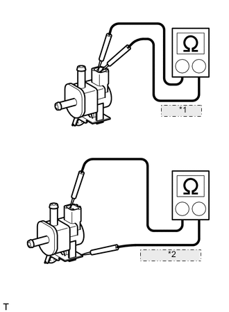
*1 23 to 26 Ω *2 10 MΩ or higher Measure the resistance according to the value(s) in the table below.
Standard resistance Tester Connection Condition Specified Condition 1 - 2 20°C (68°F) 23 to 26 Ω 1 - Body ground Always 10 MΩ or higher 2 - Body ground If the result is not as specified, replace the purge VSV.
-
Check operation of the purge VSV.
-
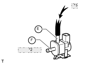
*1 Air *2 Does not flow Check that air does not flow from port E to port F.
-
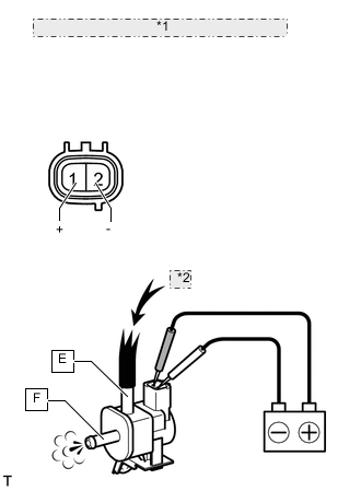
*1 Component without harness connected: (Purge VSV) *2 Air Apply battery voltage to the connector, and check the VSV operation.
OK Measurement Condition Specified Condition Battery positive (+) → Terminal 1
Battery negative (-) → Terminal 2
Air flows from port E to port F If the result is not as specified, replace the purge VSV.
-
-