EMISSION CONTROL SYSTEM ON-VEHICLE INSPECTION
PROCEDURE
-
CHECK FOR LEAK
-
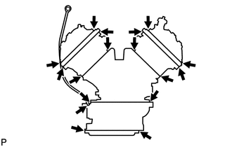
Visually check that the hoses, connections and gaskets have no cracks, leaks or damage.
Note
-
Detachment or other problems with the engine oil dipstick, filler cap, PCV hose and other components may cause the engine to run improperly.
-
Disconnection, looseness or cracks in the parts of the air induction system between the throttle body and cylinder head will allow air suction and cause an engine failure or engine malfunctions.
If the result is not as specified, replace parts as necessary.
-
-
-
CHECK FUEL CUT-OFF RPM
-
Start and warm up the engine.
-
Open the throttle valve and keep the engine speed at 2500 rpm.
-
Use a sound scope to check for injector operating noise.
-
Check that when the accelerator pedal is released, injector operation noise stops momentarily and then resumes.
If the result is not as specified, check the injector, wiring and ECM.
-
-
CHECK LINE AND CONNECTORS
-
Visually check for loose connections, sharp bends or damage.
-
-
CHECK FUEL TANK ASSEMBLY
-
Visually check for deformation, cracks or fuel leakage.
-
-
CHECK PURGE VSV
-
Connect the intelligent tester to the DLC3.
-
Turn the power switch ON (IG).
-
Push the tester main switch ON.
-
Enter the following menus: Select: Powertrain / Engine / Active Test / Activate the VSV for Evap Control.
-
Disconnect the hose (connected to the canister) from the purge VSV.
-
Start the engine.
-
Using the tester, turn off the purge VSV (EVAP VSV: OFF).
-
Use your finger to confirm that the purge VSV has no suction.
-
Using the tester, turn on the purge VSV (EVAP VSV: ON).
-
Use your finger to confirm that the purge VSV has suction.
-
-
INSPECT AIRTIGHTNESS IN FUEL TANK AND FILLER PIPE
-
Remove the floor No. 1 under cover Click here.
-

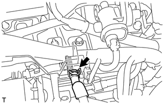
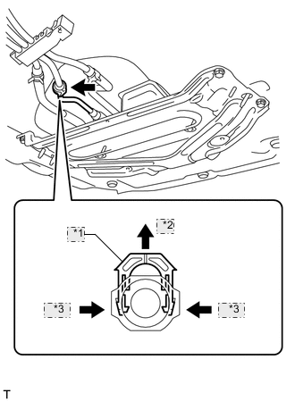
*1 Retainer *2 Up *3 Pinch Disconnect the fuel tank vent hose from the vent line tube.
-
Pinch the retainer and then raise it.
Tech Tips
Do not remove the retainer.
Note
-
Do not use any tools in this procedure.
-
Check for any dirt and foreign matter contamination in the valve and around the connector. Clean if necessary. Foreign matter may damage the O-rings or cause leaks in the seal between the valve and connector.
-
-
-
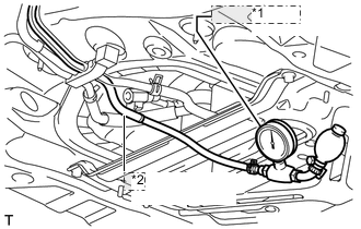
*1 Pressure Gauge *2 Vent Line Tube Connect a pressure gauge to the vent line tube.
-
Apply 4 kPa (40.7 gf/cm2, 0.6 psi) of pressure to the vent line of the fuel tank.
-
Check that the internal pressure of the fuel tank is maintained for 1 minute.
-
Check the connected portions of each hose and pipe.
-
Check the installed parts on the fuel tank.
If any malfunctions, damage or other problems are found, replace the fuel tank and filler pipe.
-

*1 Retainer *2 Push Connect the fuel tank vent hose to the vent line tube.
-
Connect the fuel tank vent hose to the vent line tube and push the retainer to lock it.
Note
-
Check for damage or foreign objects on the connected part.
-
After connecting, check that the fuel tank vent hose and the valve are securely connected by pulling on them.
-
-
-
Install the floor No. 1 under cover Click here.
-
-
CHECK FUEL CUTOFF VALVE AND FILL CHECK VALVE
-
Remove the floor No. 1 under cover Click here.
-
*1 Retainer *2 Up *3 Pinch Disconnect the fuel tank vent hose from the vent line tube.
-
Pinch the retainer and then raise it.
Tech Tips
Do not remove the retainer.
Note
-
Do not use any tools in this procedure.
-
Check for any dirt and foreign matter contamination in the valve and around the connector. Clean if necessary. Foreign matter may damage the O-rings or cause leaks in the seal between the valve and connector.
-
-
-
Connect a pressure gauge to the vent line tube.
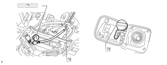
*1 Pressure Gauge *2 Fuel Tank Cap *3 Vent Line Tube -
Fill the fuel tank with fuel.
-
Apply 4 kPa (40.7 gf/cm2, 0.6 psi) of pressure to the vent line of the fuel tank.
Tech Tips
Check the amount of fuel in the fuel tank. When the fuel tank is full, the float valve of the fill check valve is closed and no air can pass through.
-
Remove the fuel tank cap, and check that the pressure drops.
If the pressure does not drop, replace the fuel tank assembly.
-
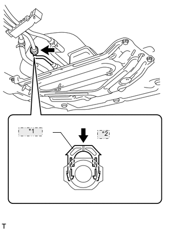
*1 Retainer *2 Push Connect the fuel tank vent hose to the vent line tube.
-
Connect the fuel tank vent hose to the vent line tube and push the retainer to lock it.
Note
-
Check for damage or foreign objects on the connected part.
-
After connecting, check that the fuel tank vent hose and the valve are securely connected by pulling on them.
-
-
-
Install the floor No. 1 under cover Click here.
-
-
CHECK AIR INLET LINE
-
Remove the floor No. 1 under cover Click here.
-
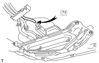
*1 Air Disconnect the air inlet line hose from the air inlet line tube.
-
Check that air flows freely into the air inlet line.
Tech Tips
If air does not flow freely into the air inlet line, repair or replace it.
-
Connect the air inlet line hose to the air inlet line tube.
-
Install the floor No. 1 under cover Click here.
-