FUEL SENDER GAUGE ASSEMBLY INSPECTION
PROCEDURE
-
INSPECT FUEL SENDER GAUGE ASSEMBLY (for LH Side)
-
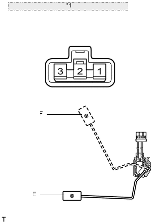
*1 Component without harness connected: (Fuel Sender Gauge) Inspect the fuel sender gauge.
-
Check that the float moves smoothly between F and E.
-
Measure the resistance according to the value(s) in the table below.
Standard resistance Tester Connection Condition Specified Condition 2 - 3 Float level is F (upper) 6.5 to 8.5 Ω Float level is E (lower) 185.8 to 189.8 Ω If the value is not as specified, replace the fuel sender gauge assembly.
-
-
-
INSPECT FUEL SENDER GAUGE ASSEMBLY (for RH Side)
-
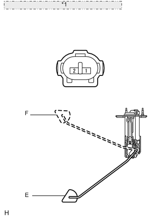
*1 Component without harness connected: (Fuel Sender Gauge) Inspect the fuel sender gauge.
-
Check that the float moves smoothly between F and E.
-
Measure the resistance according to the value(s) in the table below.
Standard resistance Tester Connection Condition Specified Condition 1 - 2 Float level is F (upper) 6.5 to 8.5 Ω Float level is E (lower) 219.7 to 224.7 Ω If the value is not as specified, replace the fuel sender gauge assembly.
-
-