FUEL TANK INSTALLATION

PROCEDURE
-
INSTALL NO. 2 FUEL TANK PROTECTOR
-
Install the No. 2 fuel tank protector to the fuel tank.
-
-
INSTALL NO. 1 FUEL TANK PROTECTOR SUB-ASSEMBLY
-
Install the No. 1 fuel tank protector to the fuel tank.
-
-
INSTALL FUEL TANK MAIN TUBE SUB-ASSEMBLY
-
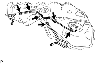
Install the fuel tube 6 clamps.
-
Install the fuel tank main tube to the fuel tank with the 6 clamps.
-
-
INSTALL FUEL TANK RETURN VENT TUBE
-
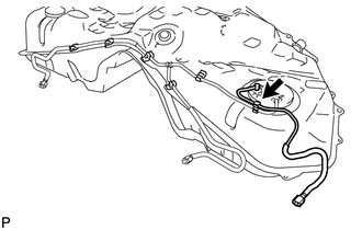
Install the fuel tank return vent tube to the fuel tank.
-
-
INSTALL FUEL TANK TO CANISTER TUBE SUB-ASSEMBLY
-
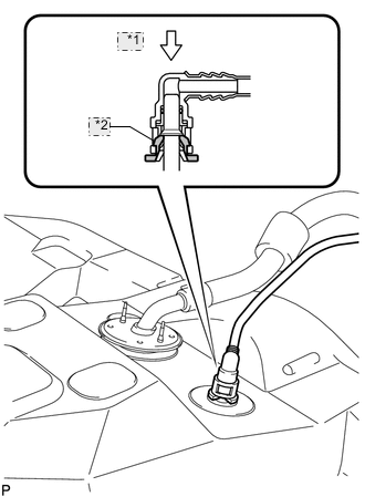
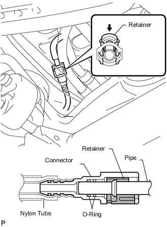
*1 Push *2 Retainer Install the canister tube to the fuel tank.
Note
-
Before installing the tube connectors to the pipes, check if there is any damage or foreign matter in the connectors.
-
After the connection, check if the connectors and pipes are securely connected by trying to pull them apart.
Tech Tips
Push the parts together firmly until a "click" sound is heard.
-
-
-
INSTALL NO. 1 FUEL TANK BREATHER TUBE SUB-ASSEMBLY
-
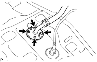
Install new gasket and the breather tube with the 4 screws.
- Torque:
- 1.5 N*m { 15 kgf*cm, 13 in.*lbf }
-
-
INSTALL FUEL TANK ASSEMBLY
-
Set the fuel tank on a engine lifter and raise the fuel tank.
Note
Do not allow the fuel tank to contact the vehicle, especially the differential.
-
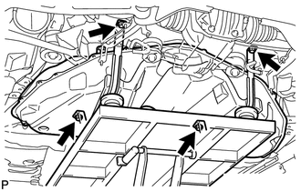
Temporarily install the 2 fuel tank bands with the 4 bolts.
-
Tighten the bolts in the front.
- Torque:
- 45 N*m { 459 kgf*cm, 33 ft.*lbf }
-
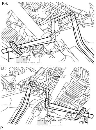
*1 Fulcrum Length Using SST, a torque wrench and union nut wrench, tighten the bolts in the rear.
- SST
- 09961-00950
- Torque:
- without SST
- 45 N*m { 459 kgf*cm, 33 ft.*lbf }
- with SST
- 22.8 N*m { 232 kgf*cm, 17 ft.*lbf }
Tech Tips
-
Use a torque wrench with a fulcrum length of 180 mm (7.09 in).
-
Make sure union nut wrench, SST and torque wrench are connected in a straight line. Fulcrum Length
-
-
CONNECT FUEL TANK TO FILLER PIPE HOSE
-
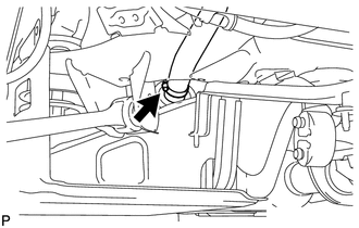
Connect the filler pipe hose to the fuel tank.
-
-
CONNECT NO. 1 FUEL TANK BREATHER TUBE SUB-ASSEMBLY
-
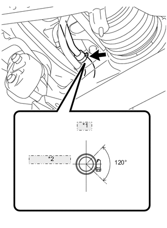
*1 Upper *2 Front Side of Vehicle Connect the breather tube.
Tech Tips
The direction of the hose clamp is indicated in the illustration.
-
-
CONNECT FUEL TANK TO CANISTER TUBE SUB-ASSEMBLY
-
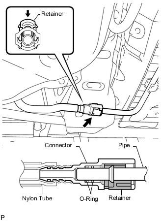
Connect the canister tube.
Note
-
Before installing the tube connectors to the pipes, check if there is any damage or foreign matter in the connectors.
-
After the connection, check if the connectors and pipes are securely connected by trying to pull them apart.
Tech Tips
Push the parts together firmly until a "click" sound is heard.
-
-
-
CONNECT FUEL TANK RETURN VENT TUBE
-
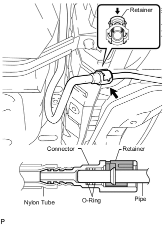
Connect the fuel tank return vent tube.
Note
-
Before installing the tube connectors to the pipes, check if there is any damage or foreign matter in the connectors.
-
After the connection, check if the connectors and pipes are securely connected by trying to pull them apart.
Tech Tips
Push the parts together firmly until a "click" sound is heard.
-
-
-
CONNECT FUEL TANK MAIN TUBE SUB-ASSEMBLY
-
Connect the fuel tank main tube LH.
Note
-
Before installing the tube connectors to the pipes, check if there is any damage or foreign matter in the connectors.
-
After the connection, check if the connectors and pipes are securely connected by trying to pull them apart.
Tech Tips
Push the parts together firmly until a "click" sound is heard.
-
-
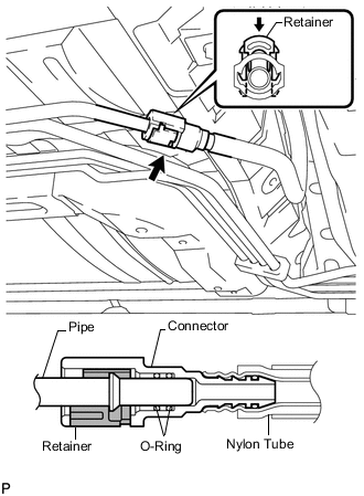
Connect the fuel tank main tube RH.
Note
-
Before installing the tube connectors to the pipes, check if there is any damage or foreign matter in the connectors.
-
After the connection, check if the connectors and pipes are securely connected by trying to pull them apart.
Tech Tips
Push the parts together firmly until a "click" sound is heard.
-
-
-
INSTALL FUEL TANK PROTECTOR BRACKET SIDE
-
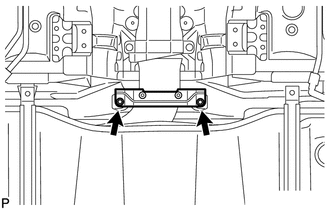
Install the protector with the 2 nuts.
- Torque:
- 5.4 N*m { 55 kgf*cm, 48 in.*lbf }
-
-
INSTALL FUEL TANK FILLER PIPE PROTECTOR
-
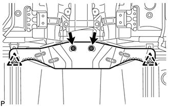
Install the protector with the 2 clips and 2 nuts.
- Torque:
- 5.4 N*m { 55 kgf*cm, 48 in.*lbf }
-
-
INSTALL PROPELLER WITH CENTER BEARING SHAFT ASSEMBLY
-
INSTALL FUEL SENDER GAUGE ASSEMBLY
-
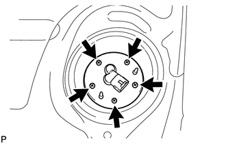
Install a new gasket and sender gauge to the fuel tank with the 5 screws.
- Torque:
- 1.5 N*m { 15 kgf*cm, 13 in.*lbf }
-
-
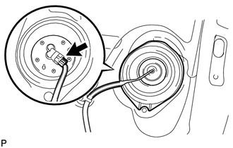
INSTALL REAR FLOOR SERVICE HOLE COVER
-
Connect the fuel sender gauge connector.
-
Install the service hole cover with new butyl tape.
-
-
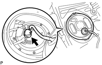
INSTALL FUEL SUCTION WITH PUMP AND GAUGE TUBE ASSEMBLY
-
Apply a light coat of gasoline to a new gasket, and install it to the fuel tank.
-
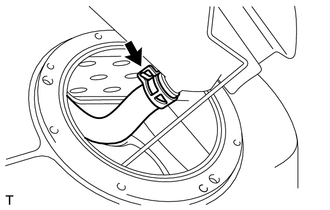
Connect the fuel hose, and install the fuel suction with pump and gauge tube to the fuel tank.
Note
-
Be careful not to bend the arm of the fuel sender gauge.
-
When connecting the fuel hose, do not forcibly pull the hose.
-
-
-
INSTALL FUEL TANK VENT TUBE SET PLATE
-
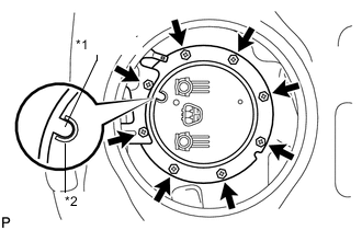
*1 Protrusion *2 Cutout Install the No. 2 fuel tank protector and set plate with the 8 bolts.
- Torque:
- 6.0 N*m { 61 kgf*cm, 53 in.*lbf }
Tech Tips
Align the protrusion of the set plate with the cutout of the fuel suction with pump and gauge tube.
-
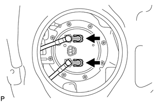
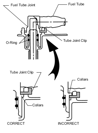
Install the fuel tank main tube and fuel tank return vent tube with the 2 tube joint clips.
Note
-
Check that there are no scratches or foreign objects on the connecting parts.
-
Check that the fuel tube joint is inserted securely.
-
Check that the tube joint clips are on the collars of the fuel tube joints.
-
After installing the tube joint clips, check that the fuel tube joints have not been pulled off.
-
-
-
INSTALL REAR FLOOR NO. 2 SERVICE HOLE COVER
-
Connect the connector.
-
Install the service hole cover with new butyl tape.
-
-
INSTALL REAR NO. 1 AND NO. 2 SEAT ADJUSTER ASSEMBLY
-
for Power Seat:
-
for Ottoman:
-
-
INSTALL REAR SEAT CUSHION ASSEMBLY (for Fixed Seat Type)
-
INSTALL SERVICE PLUG GRIP
-
CONNECT CABLE TO NEGATIVE AUXILIARY BATTERY TERMINAL
Note
When disconnecting the cable, some systems need to be initialized after the cable is reconnected Click here.
-
INSTALL BATTERY SERVICE HOLE COVER LH
-
INSTALL DECK TRIM SIDE BOARD LH (w/o Spare Tire)
-
INSTALL DECK BOARD ASSEMBLY (w/o Spare Tire)
-
INSTALL LUGGAGE COMPARTMENT MAT SUB-ASSEMBLY (w/ Spare Tire)
-
ADD FUEL
-
INSPECT FOR FUEL LEAK