EXHAUST MANIFOLD REMOVAL

CAUTION / NOTICE / HINT
Tech Tips
When viewed from the rear of the engine assembly, Bank 1 is on the left side and Bank 2 is on the right side.
PROCEDURE
-
REMOVE ENGINE AND TRANSMISSION
-
REMOVE FRONT FRAME ASSEMBLY
-
REMOVE ENGINE OIL LEVEL DIPSTICK GUIDE
-
REMOVE NO. 1 EXHAUST MANIFOLD HEAT INSULATOR
-

Remove the 3 bolts and heat insulator.
-
-
REMOVE NO. 2 EXHAUST MANIFOLD HEAT INSULATOR
-

Remove the 3 bolts and heat insulator.
-
-
REMOVE FRONT ENGINE MOUNTING INSULATOR
-
REMOVE FRONT NO. 1 ENGINE MOUNTING BRACKET RH
-
REMOVE FRONT NO. 1 ENGINE MOUNTING BRACKET LH
-
REMOVE EXHAUST MANIFOLD SUB-ASSEMBLY RH
-

Disconnect the air fuel ratio sensor connector.
-

Remove the 8 nuts and exhaust manifold RH.
-
Remove the gasket.
-
-
REMOVE EXHAUST MANIFOLD SUB-ASSEMBLY LH
-
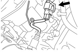
Disconnect the air fuel ratio sensor connector.
-
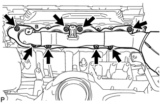
Remove the 8 nuts and exhaust manifold LH.
-
Remove the gasket.
-
-
REMOVE AIR FUEL RATIO SENSOR (for Bank 1 Sensor 1)
-
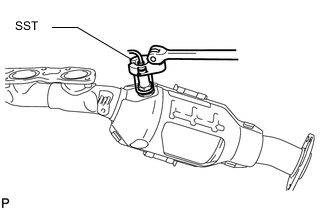
Using SST, remove the air fuel ratio sensor from the exhaust manifold LH.
- SST
- 09224-00010
-
-
REMOVE AIR FUEL RATIO SENSOR (for Bank 2 Sensor 1)
-

Using SST, remove the air fuel ratio sensor from the exhaust manifold RH.
- SST
- 09224-00010
-