FUEL PUMP(for High Pressure) INSTALLATION
CAUTION / NOTICE / HINT
Tech Tips
When viewed from the rear of the engine assembly, Bank 1 is on the left side and Bank 2 is on the right side.
PROCEDURE
-
INSTALL FUEL PUMP ASSEMBLY (for Bank 1)
-
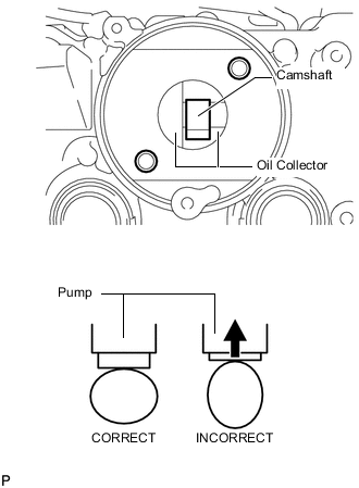
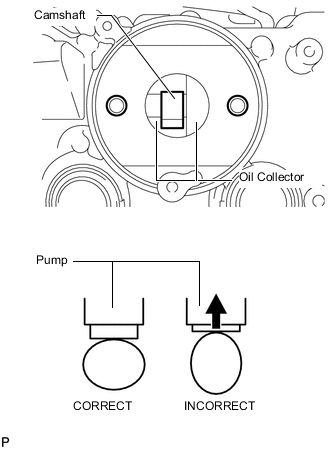
Turn the camshaft until the flat of the cam is facing the cylinder head cover's fuel pump attachment hole, as shown in the illustration.
Tech Tips
By not using the camshaft lobe to push up the pump lifter surface, it is easier to install the fuel pump and No. 3 fuel pipe later.
-
Pour 30 cc (1.8 cu. in.) of engine oil through the cylinder head cover's fuel pump attachment hole into the cylinder head oil collector.
-
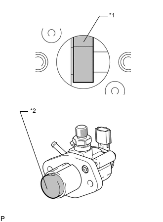
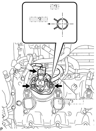
*1 Camshaft *2 Pump Lifter Apply a coat of engine oil to the pump activation cam and pump lifter.
-
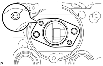
*1 Metal Eyelets Install a new fuel pump insulator to the cylinder head cover. Then pass the 2 stud bolts through the holes of the fuel pump and set it on the insulator.
Note
Install the insulator so that the open sides of the metal eyelets are facing outward, as shown in the illustration.
-
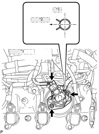
*1 Upper *2 Rear Side of Vehicle *3 No. 2 Fuel Hose Install the fuel pump with the 2 nuts.
- Torque:
- 25 N*m { 255 kgf*cm, 18 ft.*lbf }
-
Connect the No. 2 fuel hose.
Tech Tips
As shown in the illustration.
-
Connect the fuel pump connector.
-
-
INSTALL FUEL PUMP ASSEMBLY (for Bank 2)
-
Turn the camshaft until the flat of the cam is facing the cylinder head cover's fuel pump attachment hole, as shown in the illustration.
Tech Tips
By not using the camshaft lobe to push up the pump lifter surface, it is easier to install the fuel pump and No. 2 fuel pipe later.
-
Pour 30 cc (1.8 cu. in.) of engine oil through the cylinder head cover's fuel pump attachment hole into the cylinder head oil collector.
-
*1 Camshaft *2 Pump Lifter Apply a coat of engine oil to the pump activation cam and pump lifter.
-
*1 Metal Eyelets Install a new fuel pump insulator to the cylinder head cover. Then pass the 2 stud bolts through the holes of the fuel pump and set it on the insulator.
Note
Install the insulator so that the open sides of the metal eyelets are facing outward, as shown in the illustration.
-
*1 Upper *2 RH Side of Vehicle *3 No. 1 Fuel Hose Install the fuel pump with the 2 nuts.
- Torque:
- 25 N*m { 255 kgf*cm, 18 ft.*lbf }
-
Connect the No. 1 fuel hose.
Tech Tips
As shown in the illustration.
-
Connect the fuel pump connector.
-
-
INSTALL NO. 3 FUEL PIPE SUB-ASSEMBLY
-
INSTALL NO. 2 FUEL PIPE SUB-ASSEMBLY
-
INSTALL FUEL PRESSURE PULSATION DAMPER ASSEMBLY