FUEL RELIEF VALVE INSTALLATION
PROCEDURE
-
INSTALL FUEL RELIEF VALVE ASSEMBLY
-
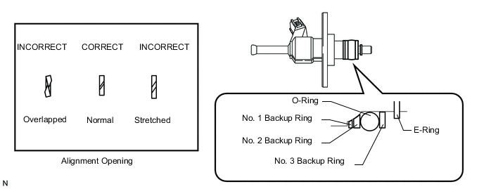
Install a new O-ring, new backup rings (No. 1, No. 2 and No. 3) and a new E-ring to the fuel relief valve as shown in the illustration.
Note
-
Check that there is no foreign matter or damaged areas in the relief valve's O-ring groove.
-
Check that the No. 1 and No. 2 backup rings are installed in the correct direction.
-
Make sure that the backup rings and O-ring are installed in the correct order.
-
Check that the alignment openings of the backup rings are not overlapped or stretched as shown in the illustration.
-
After installing the O-ring, check that it is not contaminated with foreign matter and is not damaged.
-
Check that the No. 3 fuel pipe installation end is not contaminated with foreign matter and is not damaged.
-
-
Fix the delivery pipe between aluminum plates in a vise.
Note
Do not overtighten the vise.
-
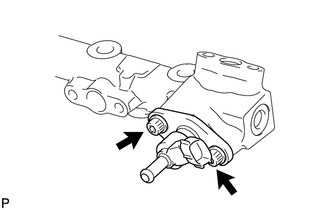
Apply engine oil to the O-ring. Using a 5 mm hexagon socket wrench, install the fuel relief valve to the fuel delivery pipe with the 2 bolts.
- Torque:
- 9.0 N*m { 92 kgf*cm, 80 in.*lbf }
Note
Make sure there is no gasoline on the O-ring and inside the installation hole.
-
-
INSTALL FUEL DELIVERY PIPE
-
INSTALL NO. 4 FUEL PIPE SUB-ASSEMBLY
-
INSTALL NO. 2 ENGINE COVER SUB-ASSEMBLY LH
-
INSTALL NO. 2 ENGINE COVER SUB-ASSEMBLY
-
INSTALL NO. 1 ENGINE COVER SUB-ASSEMBLY
-
INSTALL NO. 2 FUEL PIPE SUB-ASSEMBLY
-
INSTALL FUEL PRESSURE PULSATION DAMPER ASSEMBLY