FUEL PRESSURE PULSATION DAMPER INSTALLATION

CAUTION / NOTICE / HINT
Tech Tips
When viewed from the rear of the engine assembly, Bank 1 is on the left side and Bank 2 is on the right side.
Note
While the auxiliary battery is connected, even if the power switch is off, the brake control system activates when the brake pedal is depressed or the door courtesy switch turns on. Therefore during servicing of the brake system components, do not operate the brake pedal and open / close the doors while the battery is connected.
PROCEDURE
-
INSTALL FUEL PRESSURE PULSATION DAMPER ASSEMBLY
-
Apply a light coat of engine oil to the threads and gasket seating surfaces of the 2 fuel pressure pulsation damper assemblies.
-
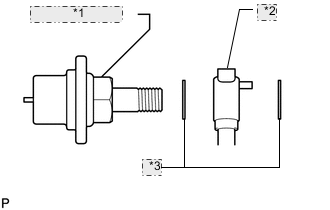
*1 Pulsation Damper *2 Fuel Pipe *3 Gasket Temporarily install each dampers together with 2 new gaskets and the fuel pipe to the fuel pump.
-

Install the 2 clamp bolts.
- Torque:
- 10 N*m { 102 kgf*cm, 7 ft.*lbf }
-
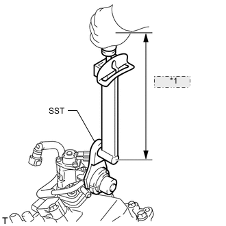
*1 Fulcrum Length Using SST, tighten the 2 dampers.
- SST
- 09612-24014 ( 09617-24011 )
- Torque:
- without SST
- 36 N*m { 367 kgf*cm, 27 ft.*lbf }
- with SST
- 31 N*m { 313 kgf*cm, 23 ft.*lbf }
Tech Tips
-
Use a torque wrench with a fulcrum length of 300 mm (11.8 in.). When using a torque wrench with a fulcrum length that is not 300 mm (11.8 in.), calculate the torque specification for the torque wrench and SST based on the "without SST" torque specification Click here.
-
Make sure SST and the torque wrench are connected in a straight line.
-

Connect the 3 fuel hoses.
-

*1 for Bank 1: *2 for Bank 2: Connect the 2 delivery pipe connectors to the delivery pipe.
-
-
CONNECT NO. 1 FUEL HOSE
-
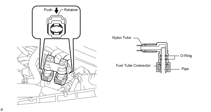
Push in the tube connector to the pipe until the tube connector makes a "click" sound.
-
Push down on the retainer to lock it in place.
Note
-
Check that there is no damage or foreign objects on the connected part of the fuel pipe.
-
After connecting, check that the fuel tube connector and the pipe are securely connected by pulling on them.
-
-
-
INSTALL NO. 6 COVER SUB-ASSEMBLY (for RHD)
-
Install the No. 6 cover.
-
-
INSTALL ENGINE COVER SUB-ASSEMBLY LH (for RHD)
-

*1 Engine Cover LH *2 No. 6 Cover Install the engine cover LH with the 4 nuts.
- Torque:
- 21 N*m { 214 kgf*cm, 15 ft.*lbf }
-
-
INSTALL NO. 5 COVER SUB-ASSEMBLY (for LHD)
-
Install the No. 5 cover.
-
-
INSTALL ENGINE COVER SUB-ASSEMBLY RH (for LHD)
-

*1 Engine Cover RH *2 No. 5 Cover Install the engine cover RH with the 4 nuts.
- Torque:
- 21 N*m { 214 kgf*cm, 15 ft.*lbf }
-
-
INSTALL ENGINE OIL LEVEL DIPSTICK GUIDE
-
INSTALL INVERTER COOLING PIPE BRACKET (for RHD)
-
CONNECT FRAME WIRE (for RHD)
-
Attach the 2 claws of the frame wire to the No. 1 relay block.
-

Install the frame wire to the No. 1 relay block with the 2 nuts.
- Torque:
- 13 N*m { 130 kgf*cm, 10 ft.*lbf }
-
Install the No. 1 relay block cover.
-
-
CONNECT GENERATOR CABLE (for RHD)
-
CONNECT MOTOR CABLE (for RHD)
-
INSTALL INVERTER TERMINAL COVER (for RHD)
-
CONNECT FRAME WIRE (for LHD)
-
Attach the 2 claws of the frame wire to the No. 1 relay block.
-

Install the frame wire to the No. 1 relay block with the 2 nuts.
- Torque:
- 13 N*m { 130 kgf*cm, 10 ft.*lbf }
-
Install the No. 1 relay block cover.
-
-
CONNECT INLET INVERTER COOLING PIPE (for LHD)
-
CONNECT GENERATOR CABLE (for LHD)
-
CONNECT MOTOR CABLE (for LHD)
-
INSTALL INVERTER TERMINAL COVER (for LHD)
-
INSTALL INVERTER COVER ASSEMBLY LH (for RHD)
-
INSTALL MOTOR CABLE COVER LH (for RHD)
-
INSTALL COWL TOP VENTILATOR LOUVER LH (for RHD)
-
INSTALL INVERTER COVER ASSEMBLY RH (for LHD)
-
INSTALL MOTOR CABLE COVER RH (for LHD)
-
INSTALL COWL TOP VENTILATOR LOUVER RH (for LHD)
-
INSTALL INTAKE MANIFOLD
-
INSPECT FOR FUEL LEAK