CYLINDER HEAD REASSEMBLY

CAUTION / NOTICE / HINT
Tech Tips
When viewed from the rear of the engine assembly, Bank 1 is on the left side and Bank 2 is on the right side.
PROCEDURE
-
INSTALL STUD BOLT
Note
If the stud bolts are deformed or their threads are damaged, replace them.
-
Using E7 and E8 "TORX" socket wrenches, install the stud bolts.
- Torque:
- for stud bolts A, B, C and D
- 9.0 N*m { 92 kgf*cm, 80 in.*lbf }
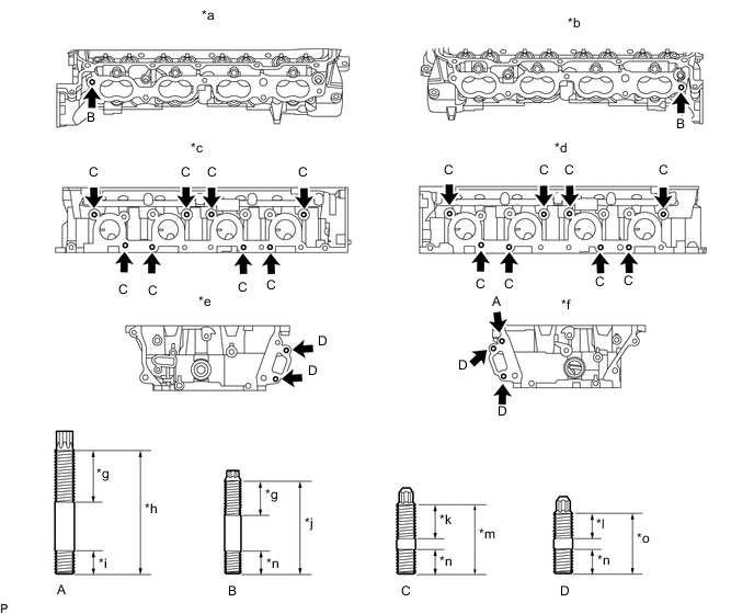
Text in Illustration *a for Bank 2 Intake Side *b for Bank 1 Intake Side *c for Bank 2 Exhaust Side *d for Bank 1 Exhaust Side *e for Bank 2 Front Side *f for Bank 1 Front Side *g 24 mm (0.945 in.) *h 52 mm (2.05 in.) *i 12 mm (0.472 in.) *j 45 mm (1.77 in.) *k 20 mm (0.787 in.) *l 14 mm (0.551 in.) *m 35 mm (1.38 in.) *n 13 mm (0.512 in.) *o 29 mm (1.14 in.) - -
-
-
INSTALL NO. 2 STRAIGHT SCREW PLUG
-
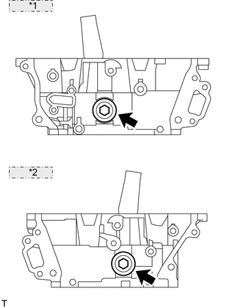
*1 for Bank 2: *2 for Bank 1: Using a 14 mm hexagon wrench, install 2 new gaskets and the 2 straight screw plugs.
- Torque:
- 85 N*m { 867 kgf*cm, 63 ft.*lbf }
-
-
INSTALL NO. 1 STRAIGHT SCREW PLUG
-
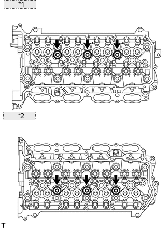
*1 for Bank 2: *2 for Bank 1: Using a 10 mm hexagon wrench, install 6 new gaskets and the 6 straight screw plugs.
- Torque:
- 44 N*m { 449 kgf*cm, 32 ft.*lbf }
-
-
INSTALL VALVE SPRING SEAT
-
Install the valve spring seats to the cylinder head.
-
-
INSTALL VALVE STEM OIL SEAL
-
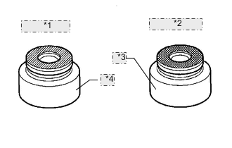
*1 Intake Side: *2 Exhaust Side: *3 Gray *4 Brown Apply a light coat of engine oil to new oil seals.
Note
Pay attention when installing the intake and exhaust oil seals. For example, installing the intake oil seal into the exhaust side or installing the exhaust oil seal to the intake side can cause installation problems later.
Tech Tips
The intake valve oil seals are brown and the exhaust valve oil seals are gray.
-
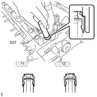
*1 CORRECT *2 INCORRECT Using SST, push in the oil seals.
- SST
- 09201-41020
Note
Failure to use SST will cause the seal to be damaged or improperly seated.
-
-
INSTALL INTAKE VALVE
-
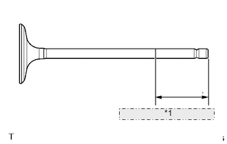
*1 40 mm (1.57 in.) or more Apply plenty of engine oil to the tip area of the intake valve shown in the illustration.
-
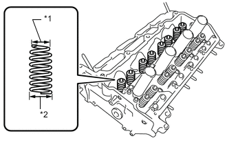
*1 Narrow *2 Wide Install the valve, compression spring and spring retainer to the cylinder head.
Note
-
Install the same parts in the same combination to their original locations.
-
Install the inner compression spring to the wide end of the cylinder head sub-assembly.
-
-
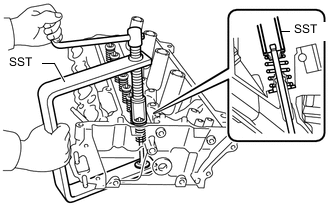
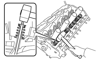
Using SST and wooden blocks, compress the spring and install the retainer lock.
- SST
- 09202-70020 ( 09202-01010, 09202-01020 )
- 09202-00021
-
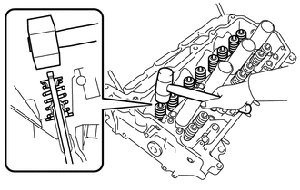
Using a plastic-faced hammer, lightly tap the valve stem tip to ensure a proper fit.
Note
-
Do not damage the valve stem tip.
-
Be careful not to damage the retainer.
-
-
-
INSTALL EXHAUST VALVE
-
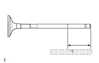
*1 40 mm (1.57 in.) or more Apply plenty of engine oil to the tip area of the exhaust valve shown in the illustration.
-
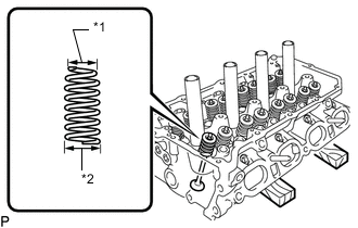
*1 Narrow *2 Wide Install the valve, compression spring and spring retainer to the cylinder head.
Note
-
Install the same parts in the same combination to their original locations.
-
Install the inner compression spring to the wide end of the cylinder head sub-assembly.
-
-
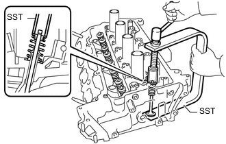
Using SST and wooden blocks, compress the spring and install the retainer lock.
- SST
- 09202-70020 ( 09202-01010, 09202-01020 )
- 09202-00021
-
Using a plastic-faced hammer, lightly tap the valve stem tip to ensure a proper fit.
Note
-
Do not damage the valve stem tip.
-
Be careful not to damage the retainer.
-
-