ENGINE UNIT INSTALLATION

CAUTION / NOTICE / HINT
Tech Tips
When viewed from the rear of the engine assembly, Bank 1 is on the left side and Bank 2 is on the right side.
PROCEDURE
-
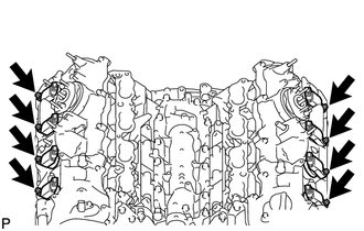
INSTALL IGNITION COIL ASSEMBLY
-
Install the 8 ignition coils with the 8 bolts.
- Torque:
- 10 N*m { 102 kgf*cm, 7 ft.*lbf }
-
-
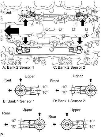
INSTALL KNOCK CONTROL SENSOR
-
Install the 4 knock control sensors with the 4 bolts so that the sensors are angled as shown in the illustration.
- Torque:
- 20 N*m { 204 kgf*cm, 15 ft.*lbf }
Note
The acceptable installation angle of the knock control sensors is between 10° above and below the horizontal position.
-
-
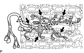
INSTALL ENGINE WIRE
-
Install the engine wire with the bolt.
- Torque:
- 10 N*m { 102 kgf*cm, 7 ft.*lbf }
-
Connect the 5 clamps and 4 connectors.
-
-
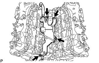
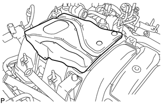
INSTALL SEPARATOR CASE
-
Install the separator case with the 4 bolts.
- Torque:
- 10 N*m { 102 kgf*cm, 7 ft.*lbf }
-
-
INSTALL FUEL INJECTOR SEAL
-
INSTALL FUEL INJECTOR ASSEMBLY (for Direct Injection)
-
INSTALL FUEL DELIVERY PIPE
-
INSTALL NO. 2 FUEL DELIVERY PIPE
-
INSTALL NO. 4 FUEL PIPE SUB-ASSEMBLY
-
INSTALL NO. 2 ENGINE COVER SUB-ASSEMBLY LH
-
INSTALL NO. 2 ENGINE COVER SUB-ASSEMBLY
-
INSTALL NO. 1 ENGINE COVER SUB-ASSEMBLY
-
INSTALL FUEL INJECTOR ASSEMBLY (for Port Injection)
-
INSTALL FUEL DELIVERY PIPE ASSEMBLY
-
INSTALL WATER INLET HOUSING
-
INSTALL FUEL PUMP ASSEMBLY (for Bank 1)
-
INSTALL FUEL PUMP ASSEMBLY (for Bank 2)
-
INSTALL NO. 3 FUEL PIPE SUB-ASSEMBLY
-
INSTALL NO. 2 FUEL PIPE SUB-ASSEMBLY
-
INSTALL FUEL PRESSURE PULSATION DAMPER ASSEMBLY
-
INSTALL FUEL TUBE SUB-ASSEMBLY
-
INSTALL INTAKE MANIFOLD ASSEMBLY
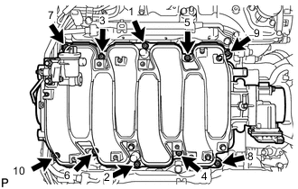
-
Install 2 new gaskets to the intake manifold.
-
Temporarily install the intake manifold with the 2 nuts and 8 bolts. Then tighten the 2 nuts and 8 bolts uniformly in the order shown in the illustration.
- Torque:
- 21 N*m { 214 kgf*cm, 15 ft.*lbf }
-
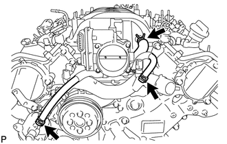
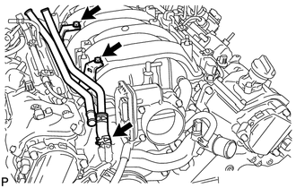
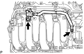
Connect the No. 1 ventilation hose and 2 water by-pass hoses as shown in the illustration.
-
-
INSTALL WATER BY-PASS PIPE SUB-ASSEMBLY
-
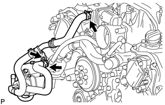
Slide the clamp to connect the water inlet hose to the front water by-pass joint.
-
Install the water by-pass pipe with the 2 bolts.
- Torque:
- 10 N*m { 102 kgf*cm, 7 ft.*lbf }
-
-
INSTALL HEATER WATER PUMP ASSEMBLY
-
Install the heater water pump with the bolt.
- Torque:
- 10 N*m { 102 kgf*cm, 7 ft.*lbf }
-
Slide the 2 clamps to connect the 2 hoses to the water by-pass pipe and water inlet housing.
-
-
INSTALL PURGE VSV
-
Install the purge VSV with the bolt.
- Torque:
- 21 N*m { 214 kgf*cm, 15 ft.*lbf }
-
Connect the purge line hose to the intake manifold.
-
-
INSTALL NO. 1 ENGINE COVER
-
INSTALL INJECTOR DRIVER
Note
-
Be careful not to drop or strike the injector driver.
-
The injector driver is grounded at the bolt and nut. To ensure that it is grounded, clean all oil and foreign matter from the installation areas of the injector driver and engine before installing the injector driver.
-
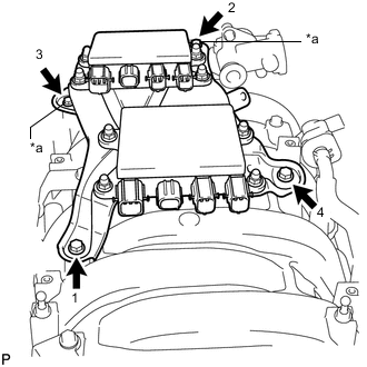
*a Nut Temporarily install the 2 injector drivers with the 2 bolts and 2 nuts.
-
Tighten the 2 bolts and 2 nuts in the order shown in the illustration.
- Torque:
- 10 N*m { 102 kgf*cm, 7 ft.*lbf }
-
-
INSTALL ENGINE WIRE
-
Engine Upper Side:
-
Connect the engine wire with the 4 nuts.
- Torque:
- 10 N*m { 102 kgf*cm, 7 ft.*lbf }
-
Install the 2 clamp brackets with the 2 bolts and connect the 2 clamps.
- Torque:
- 10 N*m { 102 kgf*cm, 7 ft.*lbf }
-
Connect the intake air control valve actuator connector.
-
Connect the purge VSV connector.
-
Connect the 2 clamps.
-
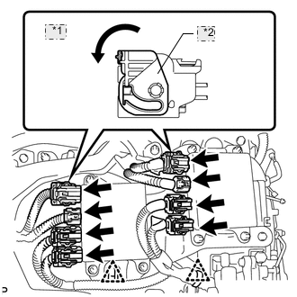
*1 Move *2 Lock Lever Connect the 8 injector driver connectors as shown in the illustration.
-
-
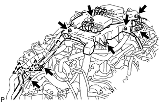
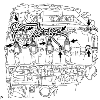
Engine Rear Side:
-
Connect the 2 ground wires with the 2 bolts.
- Torque:
- 10 N*m { 102 kgf*cm, 7 ft.*lbf }
-
Connect the 8 clamps.
-
Connect the fuel relief valve connector.
-
Connect the engine wire connector.
-
-
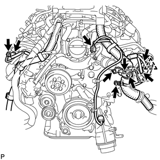
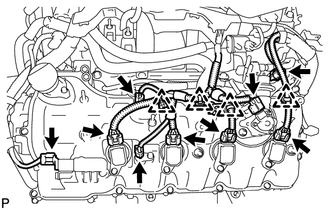
Engine RH Side:
-
Connect the 4 clamps.
-
Connect the fuel injector connector.
-
Connect the camshaft position sensor connector.
-
Connect the engine wire connector.
-
Connect the fuel pump connector (for high pressure).
-
Connect the 2 VVT sensor connectors.
-
Connect the 4 ignition coil connectors.
-
Connect the camshaft timing control valve connector.
-
-
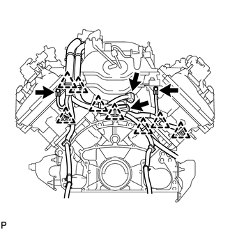
Engine Front Side:
-
Connect the 3 ground wires with the 3 bolts.
- Torque:
- 10 N*m { 102 kgf*cm, 7 ft.*lbf }
-
Connect the clamp.
-
Connect the 2 camshaft timing control motor connectors (for Bank 2).
-
Connect the 2 camshaft timing control motor connectors (for Bank 1).
-
Connect the engine coolant temperature sensor connector.
-
-
Engine LH Side:
-
Connect the 4 clamps.
-
Connect the fuel injector connector.
-
Connect the fuel pump connector (for high pressure).
-
Connect the 2 VVT sensor connectors.
-
Connect the 4 ignition coil connectors.
-
Connect the camshaft timing control valve connector.
-
-
-
INSTALL NO. 5 COVER SUB-ASSEMBLY
-
INSTALL ENGINE COVER SUB-ASSEMBLY RH
-
INSTALL NO. 6 COVER SUB-ASSEMBLY
-
INSTALL ENGINE COVER SUB-ASSEMBLY LH
-
INSTALL FRONT DIFFERENTIAL CARRIER ASSEMBLY
-
INSTALL WITH MOTOR COMPRESSOR ASSEMBLY
-
INSTALL V-RIBBED BELT