ENGINE UNIT REASSEMBLY

CAUTION / NOTICE / HINT
Tech Tips
When viewed from the rear of the engine assembly, Bank 1 is on the left side and Bank 2 is on the right side.
PROCEDURE
-
INSTALL TIMING CHAIN COVER STRAIGHT PIN
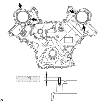
*1 5.5 to 6.5 mm
-
Install the timing chain cover straight pin.
-
Using a plastic-faced hammer, tap in new straight pins to the timing chain cover.
Standard protrusion 5.5 to 6.5 mm (0.217 to 0.256 in.)
-
-
-
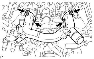
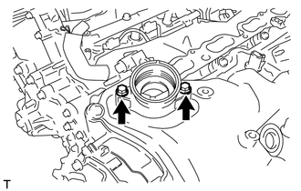
INSTALL TIMING CHAIN COVER STUD BOLT
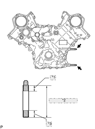
*1 23.5 mm (0.925 in.) *2 112 mm (4.41 in.) *3 23 mm (0.906 in.)
-
Install the timing chain cover stud bolt.
-
Using an E8 "TORX" socket wrench, install the 2 stud bolts as shown in the illustration.
- Torque:
- 10 N*m { 102 kgf*cm, 7 ft.*lbf }
-
-
-
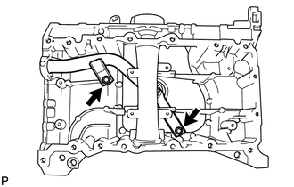
INSTALL OIL PAN STUD BOLT
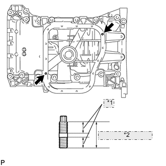
*1 9 mm (0.354 in.) *2 19 mm (0.748 in.)
-
Install the oil pan stud bolt.
-
Using an E6 "TORX" socket wrench, install the 2 stud bolts as shown in the illustration.
- Torque:
- 5.0 N*m { 51 kgf*cm, 44 in.*lbf }
-
-
-
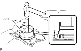
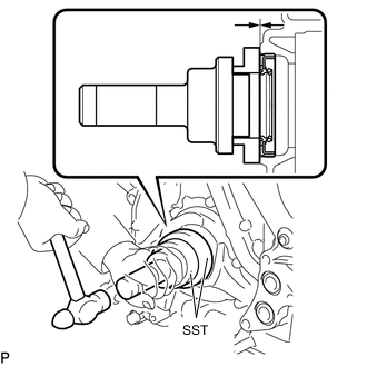
INSTALL REAR CRANKSHAFT OIL SEAL
-
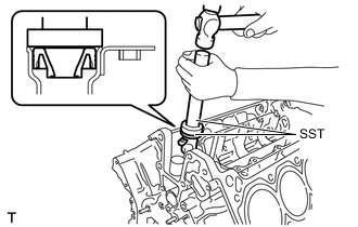
Using SST, tap in a new oil seal until its surface is flush with the oil seal retainer edge.
- SST
- 09223-15030
- 09950-70010 ( 09951-07100 )
Note
-
Keep the lip free from foreign matter.
-
Do not tap on the oil seal at an angle.
-
-
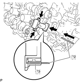
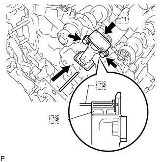
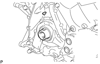
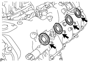
INSTALL NO. 1 VENTILATION CONNECTOR
-
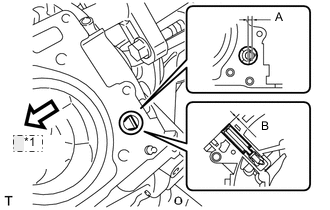
*1 Front Install the No. 1 ventilation connector as shown in the illustration.
Acceptable angle (A) -5 to 5° Tap-in depth (B) 0.2 to 3.2 mm (0.00787 to 0.126 in.) Note
After the installation of the ventilation connector, do not rotate it.
Tech Tips
Connect the No. 1 ventilation connector so that its flat surface faces the rear part of the engine.
-
-
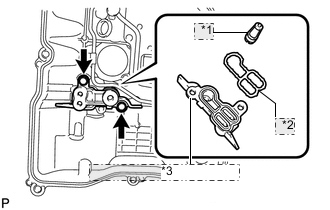
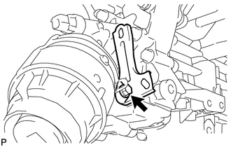
INSTALL OIL DRAIN PIPE SUB-ASSEMBLY
-
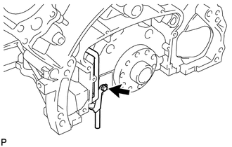
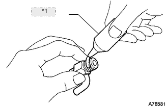
Apply a light coat of engine oil to a new O-ring.
-
Install the O-ring to the drain pipe.
-
Install the oil drain pipe with the bolt.
- Torque:
- 10 N*m { 102 kgf*cm, 7 ft.*lbf }
-
-
INSTALL ENGINE REAR OIL SEAL RETAINER
-
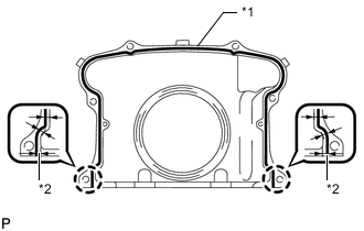
*1 2.0 to 3.0 mm *2 3.5 mm Apply seal packing in a continuous line as shown in the illustration.
Seal packing Toyota Genuine Seal Packing Black, Three Bond 1207B or equivalent Seal diameter 2.0 to 3.0 mm (0.0787 to 0.118 in.) Application position from inside edge of retainer 3.5 mm (0.138 in.) Note
-
Remove any oil from the contact surface.
-
Install the oil seal retainer within 3 minutes and tighten the bolts and nuts within 15 minutes after applying seal packing.
-
-
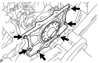
Install the oil seal retainer with the 6 bolts.
- Torque:
- 10 N*m { 102 kgf*cm, 7 ft.*lbf }
Note
-
Do not start the engine for at least 2 hours after installing.
-
When installing the oil seal retainer, make sure the lip of the oil seal is not damaged.
-
When installing the oil seal retainer, make sure the lip of the oil seal is not folded incorrectly.
-
-
INSTALL OIL STRAINER SUB-ASSEMBLY
-
Apply a light coat of engine oil to a new O-ring.
-
Install the O-ring to the oil strainer.
-
Install the oil strainer with the 2 bolts.
- Torque:
- 21 N*m { 214 kgf*cm, 15 ft.*lbf }
Note
Make sure the O-ring is not twisted or damaged.
-
-
INSTALL ENGINE OIL LEVEL SENSOR
-
INSTALL NO. 2 OIL PAN BAFFLE PLATE
-
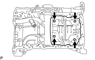
Install the baffle plate with the 4 bolts.
- Torque:
- 10 N*m { 102 kgf*cm, 7 ft.*lbf }
-
-
INSTALL NO. 1 OIL PAN BAFFLE PLATE
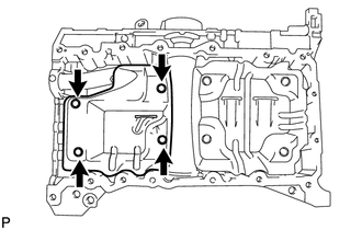
Install the baffle plate with the 4 bolts.
- Torque:
- 10 N*m { 102 kgf*cm, 7 ft.*lbf }
-
INSTALL NO. 1 OIL PAN SUB-ASSEMBLY
-
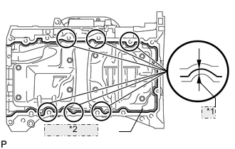
*1 6.0 mm *2 3.0 to 4.0 mm Apply seal packing in a continuous line as shown in the illustration.
Seal packing Toyota Genuine Seal Packing Black, Three Bond 1207B or equivalent Standard seal diameter 3.0 to 4.0 mm (0.118 to 0.157 in.) Application position from inside edge of oil pan 6.0 mm (0.236 in.) Note
-
Remove any oil from the contact surface.
-
Install the oil pan within 3 minutes and tighten the bolts and nuts within 15 minutes after applying seal packing.
-
-
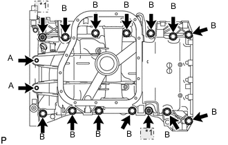
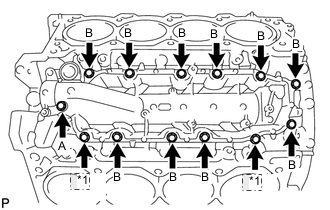
*1 Nut Install the oil pan with the 14 bolts and 2 nuts.
- Torque:
- for bolt A
- 10 N*m { 102 kgf*cm, 7 ft.*lbf }
- for bolt B
- 35 N*m { 357 kgf*cm, 26 ft.*lbf }
- for nut
- 35 N*m { 357 kgf*cm, 26 ft.*lbf }
Note
Do not start the engine for at least 2 hours after installing.
-
-
INSTALL NO. 2 OIL PAN SUB-ASSEMBLY
-
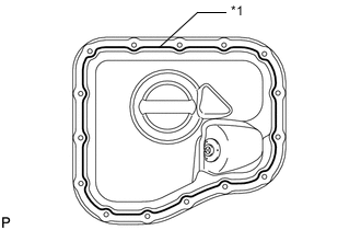
*1 3.0 to 4.0 mm Apply seal packing in a continuous line as shown in the illustration.
Seal packing Toyota Genuine Seal Packing Black, Three Bond 1207B or equivalent Standard seal diameter 3.0 to 4.0 mm (0.118 to 0.157 in.) Note
-
Remove any oil from the contact surface.
-
Install the oil pan within 3 minutes and tighten the bolts and nuts within 10 minutes after applying seal packing.
-
-
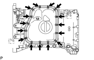
*1 Nut Install the oil pan with the 13 bolts and 2 nuts.
- Torque:
- 10 N*m { 102 kgf*cm, 7 ft.*lbf }
Note
Do not start the engine for at least 2 hours after installing.
-
-
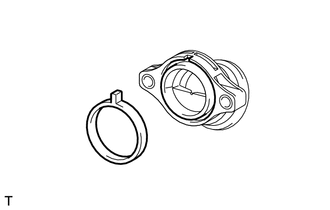
INSTALL VENTILATION PIPE GASKET
-
Using SST, evenly tap in a new ventilation pipe gasket until its surface is flush with the lip of the ventilation pipe.
- SST
- 09950-60010 ( 09951-00360 )
- 09950-70010 ( 09951-07100 )
Note
-
Do not tap the gasket at an angle.
-
Do not tap the gasket excessively.
-
-
INSTALL NO. 1 HEAT EXCHANGER COVER
-
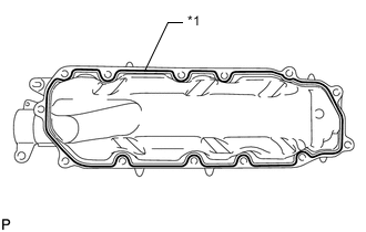
*1 3.0 to 4.0 mm Apply seal packing in a continuous line as shown in the illustration.
Seal packing Toyota Genuine Seal Packing 1282B, Three Bond 1282B or equivalent Standard seal diameter 3.0 to 4.0 mm (0.118 to 0.157 in.) Note
-
Remove any oil from the contact surface.
-
Install the heat exchanger cover within 3 minutes and tighten the bolts and nuts within 15 minutes after applying seal packing.
-
-
*1 Nut Install the heat exchanger cover with the 11 bolts and 2 nuts.
- Torque:
- for bolt A and B
- 21 N*m { 214 kgf*cm, 15 ft.*lbf }
- for nut
- 21 N*m { 214 kgf*cm, 15 ft.*lbf }
Bolt length Item Length Thread diameter Bolt A 70 mm (2.76 in.) 8 mm (0.315 in.) Bolt B 20 mm (0.787 in.) 8 mm (0.315 in.) Note
Do not start the engine for at least 2 hours after installing.
-
-
INSTALL NO. 2 OIL RETURN PIPE
-
Apply adhesive to a new return pipe.
Adhesive Toyota Genuine Adhesive 1324, Three Bond 1324 or equivalent -
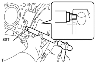
Using SST and a hammer, tap in the return pipe.
- SST
- 09950-60010 ( 09951-00300 )
- 09950-70010 ( 09951-07100 )
-
-
INSTALL OIL RETURN PIPE SUB-ASSEMBLY
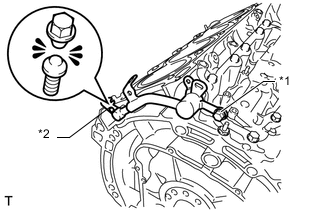
*1 Bolt B *2 Bolt A
-
Apply a light coat of engine oil to a new O-ring.
-
Install the O-ring to the return pipe.
-
Insert the oil return pipe into the No. 2 oil return pipe, and then temporarily install bolt B.
-
Install and tighten a new bolt A until the bolt head breaks off.
-
Tighten bolt B.
- Torque:
- 10 N*m { 102 kgf*cm, 7 ft.*lbf }
-
-
INSTALL CYLINDER BLOCK WATER JACKET SPACER
-
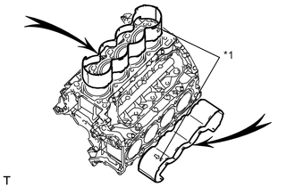
*1 "UP"Mark Install the 2 water jacket spacers as shown in the illustration.
Tech Tips
-
Face the cutouts (indicated by the arrows in the illustration) away from the engine.
-
Face the "up mark" as shown in the illustration.
-
-
-
INSTALL CYLINDER HEAD SUB-ASSEMBLY LH
-
INSTALL CYLINDER HEAD SUB-ASSEMBLY RH
-
INSTALL VALVE STEM CAP
-
Apply a light coat of engine oil to the valve stem caps.
-
Install the 32 valve stem caps to the cylinder head.
-
-
INSTALL VALVE LASH ADJUSTER ASSEMBLY
-
Be sure to inspect the valve lash adjuster before installing it Click here.
-
Install the 32 valve lash adjusters to the cylinder head.
Note
Install the lash adjuster to the same place it was removed from.
-
-
INSTALL NO. 1 VALVE ROCKER ARM SUB-ASSEMBLY
-
Apply engine oil to the lash adjuster tips and valve stem cap ends.
-
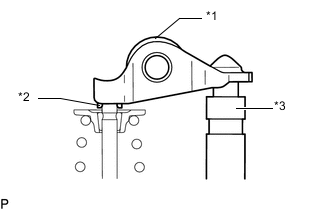
Text in Illustration *1 No. 1 Valve Rocker Arm Sub-assembly *2 Valve Stem Cap *3 Valve Lash Adjuster Assembly Install the 32 valve rocker arms as shown in the illustration.
-
-
INSTALL CAMSHAFT BEARING CAP LH
-
INSTALL CAMSHAFT HOUSING SUB-ASSEMBLY LH
-
INSTALL CAMSHAFT BEARING CAP RH
-
INSTALL CAMSHAFT HOUSING SUB-ASSEMBLY RH
-
INSTALL CRANKSHAFT TIMING GEAR KEY
-
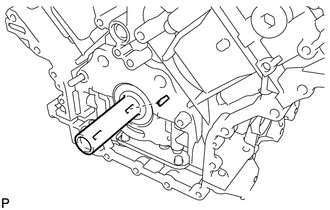
Install the timing gear key.
Tech Tips
The other timing gear key will be installed at a later step.
-
-
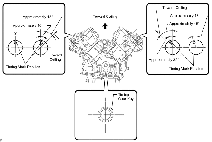
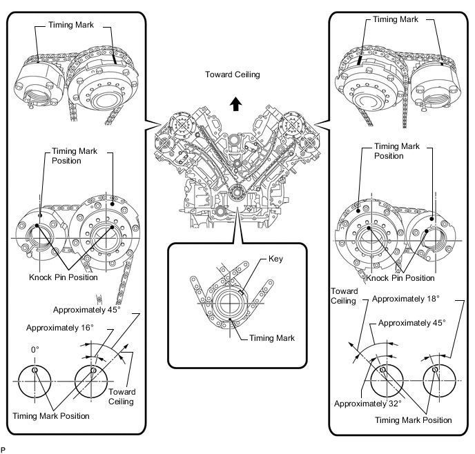
SET NO. 1 CYLINDER TO TDC / COMPRESSION
-
Temporarily install the crankshaft pulley bolt.
-
Rotate the crankshaft so that the timing gear key is as shown in the illustration. Then using a wrench, rotate each camshaft so that the timing marks are as shown in the illustration.
Note
When the crankshaft or a camshaft is rotated excessively, the valves and pistons may interfere with each other.
-
Remove the crankshaft pulley bolt.
-
-
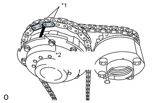
INSTALL NO. 2 CHAIN TENSIONER ASSEMBLY
-
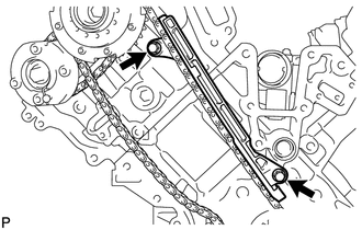
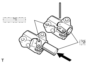
*1 Push *2 Pin *3 Plunger Install the chain tensioner with the 2 bolts.
- Torque:
- 10 N*m { 102 kgf*cm, 7 ft.*lbf }
-
While raising up the No. 2 chain tensioner, insert a pin with a diameter of 1.0 mm (0.0394 in.) into the hole to fix it in place.
-
-
INSTALL NO. 1 CHAIN SUB-ASSEMBLY RH
-
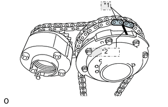
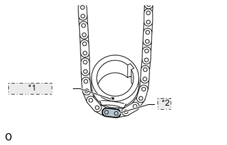
*1 Mark Plate *2 Timing Mark Align the No. 1 chain's orange mark plates with the camshaft timing gear's timing mark, and attach the chain to the gear as shown in the illustration.
-
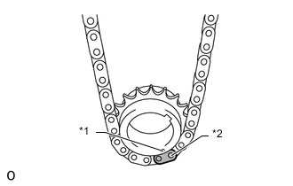
*1 Timing Mark *2 Mark Plate Align the No. 1 chain's orange mark plate with the crankshaft timing gear's timing mark, and attach the chain to the gear as shown in the illustration.
-
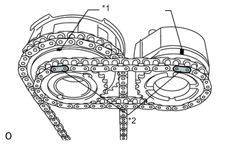
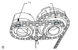
*1 Timing Mark *2 Mark Plate Align the No. 2 chain's yellow mark plates with the timing marks of the camshaft timing gear assembly and camshaft timing exhaust gear assembly, and attach the No. 2 chain to the gears as shown in the illustration.
Tech Tips
The crankshaft timing sprocket RH and camshaft exhaust gear will be installed with the No. 1 and No. 2 chains connected to the gears.
-
Install the crankshaft timing sprocket RH to the crankshaft.
-
Align and attach the knock pin of the No. 1 camshaft with the pin hole of the camshaft timing gear.
-
Using the hexagonal portion of the No. 2 camshaft, align and attach the knock pin of the No. 2 camshaft with the pin hole of the camshaft timing exhaust gear.
-
Remove the pin from the No. 2 chain tensioner.
-
Using a wrench to hold the hexagonal portion of the No. 1 camshaft, temporarily install a new bolt, with a 12 mm socket hexagon wrench.
-
Using a wrench to hold the hexagonal portion of the No. 2 camshaft, temporarily install the bolt.
-
-
INSTALL NO. 1 CHAIN VIBRATION DAMPER RH
-
Install the vibration damper with the 2 bolts.
- Torque:
- 21 N*m { 214 kgf*cm, 15 ft.*lbf }
-
-
INSTALL NO. 1 CHAIN TENSIONER SLIPPER RH
Tech Tips
If you cannot install the chain tensioner slipper due to the tension of the chain, use the hexagonal portion of the camshaft to loosen the chain, and then install the chain tensioner slipper.
-
INSTALL NO. 1 CHAIN TENSIONER ASSEMBLY RH
-
*1 Stopper Plate *2 Plunger Move the stopper plate clockwise to release the lock, and push the plunger deep into the tensioner.
-
Move the stopper plate counterclockwise to set the lock, and insert a hexagon wrench into the hole of the stopper plate.
-
Install the chain tensioner with the 2 bolts.
- Torque:
- 10 N*m { 102 kgf*cm, 7 ft.*lbf }
-
Remove the hexagon wrench from the chain tensioner.
-
-
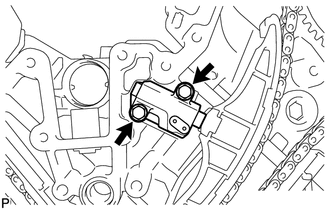
INSTALL NO. 3 CHAIN TENSIONER ASSEMBLY
-
*1 Push *2 Pin *3 Plunger Install the chain tensioner with the 2 bolts.
- Torque:
- 10 N*m { 102 kgf*cm, 7 ft.*lbf }
-
While pushing down the No. 3 chain tensioner, insert a pin with a diameter of 1.0 mm (0.0394 in.) into the hole to fix it in place.
-
-
INSTALL NO. 1 CHAIN SUB-ASSEMBLY LH
-
*1 Mark Plate *2 Timing Mark Align the No. 1 chain's orange mark plates with the camshaft timing gear's timing mark, and attach the chain to the gear as shown in the illustration.
-
*1 Timing Mark *2 Mark Plate Align the No. 1 chain's orange mark plate with the crankshaft timing gear's timing mark, and attach the chain to the gear as shown in the illustration.
-
*1 Timing Mark *2 Mark Plate Align the No. 2 chain's yellow mark plates with the timing marks of the camshaft timing gear assembly and camshaft timing exhaust gear assembly, and attach the No. 2 chain to the gears as shown in the illustration.
Tech Tips
The crankshaft timing sprocket LH and camshaft exhaust gear will be installed with the No. 1 and No. 2 chains connected to the gears.
-
Install the crankshaft timing sprocket LH to the crankshaft.
-
Align and attach the knock pin of the No. 3 camshaft with the pin hole of the camshaft timing gear.
-
Using the hexagonal portion of the No. 4 camshaft, align and attach the knock pin of the No. 4 camshaft with the pin hole of the camshaft timing exhaust gear.
Note
Because the gears' timing mark positions may shift due to looseness of the No. 1 chain, use the hexagonal portion of the camshaft to hold the No. 3 camshaft in place until the No. 1 chain tensioner is installed.
-
Remove the pin from the No. 2 chain tensioner.
-
Using a wrench to hold the hexagonal portion of the No. 3 camshaft, temporarily install a new bolt, with a 12 mm socket hexagon wrench.
-
Using a wrench to hold the hexagonal portion of the No. 4 camshaft, temporarily install the bolt.
-
-
INSTALL NO. 1 CHAIN TENSIONER SLIPPER LH
Tech Tips
If you cannot install the chain tensioner slipper due to the tension of the chain, use the hexagonal portion of the camshaft to loosen the chain, and then install the chain tensioner slipper.
-
INSTALL NO. 1 CHAIN TENSIONER ASSEMBLY LH
-
*1 Stopper Plate *2 Plunger Move the stopper plate clockwise to release the lock, and push the plunger deep into the tensioner.
-
Move the stopper plate counterclockwise to set the lock, and insert a hexagon wrench into the hole of the stopper plate.
-
Install the chain tensioner and a new gasket with the 2 bolts.
- Torque:
- 10 N*m { 102 kgf*cm, 7 ft.*lbf }
-
-
INSTALL NO. 1 CHAIN VIBRATION DAMPER LH
-

Install the vibration damper with the 2 bolts.
- Torque:
- 21 N*m { 214 kgf*cm, 15 ft.*lbf }
-
Remove the hexagon wrench from the No. 1 chain tensioner.
-
-
TIGHTEN CAMSHAFT TIMING GEAR ASSEMBLY
-
for Bank 1:
-
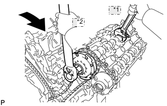
*1 Hold *2 Turn Using a wrench, hold the hexagonal portion of the No. 3 camshaft.
-
Using a 12 mm socket hexagon wrench, tighten the bolt of the camshaft timing gear.
- Torque:
- 79 N*m { 806 kgf*cm, 58 ft.*lbf }
-
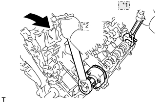
*1 Hold *2 Turn Using a wrench to hold the hexagonal portion of the No. 4 camshaft, tighten the bolt of the camshaft timing exhaust gear.
- Torque:
- 100 N*m { 1020 kgf*cm, 74 ft.*lbf }
-
-
for Bank 2:
-
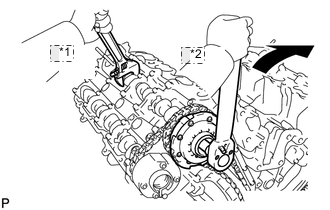
*1 Hold *2 Turn Using a wrench, hold the hexagonal portion of the No. 1 camshaft.
-
Using a 12 mm socket hexagon wrench, tighten the bolt of the camshaft timing gear.
- Torque:
- 79 N*m { 806 kgf*cm, 58 ft.*lbf }
-
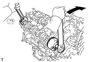
*1 Hold *2 Turn Using a wrench to hold the hexagonal portion of the No. 2 camshaft, tighten the bolt of the camshaft timing exhaust gear.
- Torque:
- 100 N*m { 1020 kgf*cm, 74 ft.*lbf }
-
-
-
CHECK NO. 1 CYLINDER TO TDC / COMPRESSION
-
Temporarily install the crankshaft pulley bolt.
-
Rotate the crankshaft clockwise, and check that the timing marks on the crankshaft timing gear and camshaft timing gears are as shown in the illustration.
-
Remove the crankshaft pulley bolt.
-
-
INSTALL WATER INLET PIPE
-
INSTALL WATER PUMP
-
INSTALL TIMING CHAIN COVER SUB-ASSEMBLY
-
INSTALL FRONT CRANKSHAFT OIL SEAL
-
Apply MP grease to the lip of a new oil seal.
-
Using SST and a hammer, tap in the oil seal to a depth between 0 to 1.0 mm (0 to 0.0394 in.) from the timing chain cover edge.
- SST
- 09223-22010
- 09506-35010
Note
-
Keep the lip free from foreign matter.
-
Do not tap the oil seal at an angle.
-
-
INSTALL CRANKSHAFT TIMING GEAR KEY
-
Install the crankshaft timing gear key to the crankshaft.
-
-
INSTALL OIL CONTROL VALVE FILTER
-
for LH:
-
*1 Filter *2 Gasket *3 Cylinder Head Cover Spacer Install the valve filter to the cylinder head.
-
Install a new gasket and the cylinder head cover spacer with the 2 bolts.
- Torque:
- 10 N*m { 102 kgf*cm, 7 ft.*lbf }
-
-
for RH:
-
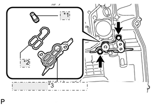
*1 Filter *2 Gasket *3 Cylinder Head Cover Spacer Install the valve filter to the cylinder head.
-
Install a new gasket and the cylinder head cover spacer with the 2 bolts.
- Torque:
- 10 N*m { 102 kgf*cm, 7 ft.*lbf }
-
-
-
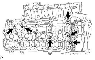
INSTALL CYLINDER HEAD COVER SUB-ASSEMBLY LH
-
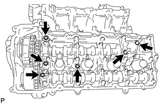
Install 4 new gaskets and 2 new O-rings to the camshaft bearing caps (No. 2, No. 3 and No. 7).
-
Install a new gasket to the cylinder head cover.
Note
Remove any oil from the contact surface.
-
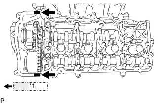
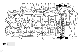
*1 Seal packing Apply seal packing as shown in the illustration.
Seal packing Toyota Genuine Seal Packing Black, Three Bond 1207B or equivalent Standard Seal diameter 2.0 to 3.0 mm (0.0787 to 0.118 in.) Note
-
Remove any oil from the contact surface.
-
Install the cylinder head cover within 3 minutes and tighten the bolts within 15 minutes after applying seal packing.
-
-
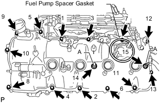
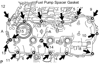
Install the cylinder head cover and 2 new seal washers with the 15 bolts in the order shown in the illustration.
- Torque:
- for bolt A
- 21 N*m { 214 kgf*cm, 15 ft.*lbf }
- except bolt A
- 12 N*m { 122 kgf*cm, 9 ft.*lbf }
Note
Do not start the engine for at least 2 hours after the installation.
-
Install a new fuel pump spacer gasket.
Note
After pressing in the fuel pump spacer gasket, make sure the gasket protrudes 1 mm (0.0394 in) or less from the cylinder head cover.
-
Install the fuel pump spacer.
-
-
INSTALL CYLINDER HEAD COVER SUB-ASSEMBLY RH
-
Install 4 new gaskets and 2 new O-rings to the camshaft bearing caps. (No. 1, No. 3 and No. 6).
-
Install a new gasket to the cylinder head cover.
Note
Remove any oil from the contact surface.
-
*1 Seal packing Apply seal packing as shown in the illustration.
Seal packing Toyota Genuine Seal Packing Black, Three Bond 1207B or equivalent Standard Seal diameter 2.0 to 3.0 mm (0.0787 to 0.118 in.) Note
-
Remove any oil from the contact surface.
-
Install the cylinder head cover within 3 minutes and tighten the bolts within 15 minutes after applying seal packing.
-
-
Install the cylinder head cover and 2 new seal washers with the 15 bolts in the order shown in the illustration.
- Torque:
- for bolt A
- 21 N*m { 214 kgf*cm, 15 ft.*lbf }
- except bolt A
- 12 N*m { 122 kgf*cm, 9 ft.*lbf }
Note
Do not start the engine for at least 2 hours after the installation.
-
Install a new fuel pump spacer gasket.
Note
After pressing in the fuel pump spacer gasket, make sure the gasket protrudes 1 mm (0.0394 in) or less from the cylinder head cover.
-
Install the fuel pump spacer.
-
-
INSTALL SPARK PLUG TUBE GASKET
-
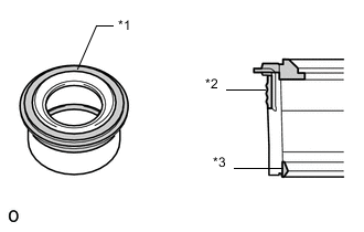
*1 Upper Surface *2 Outer Lip *3 Inner Lip Visual check the spark plug tube gasket.
OK Inspection Area Specified Condition Upper surface No scratches or deformation Outer lip No scratches or deformation Inner lip No scratches If the result is not as specified, replace the spark plug tube gasket.
-
Install the 8 plug tube gaskets to the cylinder head covers.
Note
After pressing in the spark plug tube gasket, make sure the gasket protrudes 1 mm (0.0394 in) or less from the cylinder head cover.
-
-
INSTALL CRANKSHAFT PULLEY
-
INSTALL FRONT WATER BY-PASS JOINT
-
Install the 2 new gaskets and water by-pass joint with the 4 nuts.
- Torque:
- 21 N*m { 214 kgf*cm, 15 ft.*lbf }
-
-
INSTALL WATER PUMP PULLEY
-
INSTALL OIL FILTER BRACKET
-
INSTALL OIL FILTER ELEMENT
-
INSTALL WIRE HARNESS CLAMP BRACKET
-
Install the wire harness clamp bracket with the bolt.
- Torque:
- 10 N*m { 102 kgf*cm, 7 ft.*lbf }
-
-
INSTALL CAMSHAFT TIMING CONTROL WITH EDU MOTOR ASSEMBLY RH
-
INSTALL CAMSHAFT TIMING CONTROL WITH EDU MOTOR ASSEMBLY LH
-
INSTALL CYLINDER BLOCK WATER DRAIN COCK SUB-ASSEMBLY
-
*1 Adhesive Apply adhesive to 2 or 3 threads of the drain cock.
Adhesive Toyota Genuine Adhesive 1344, Three Bond 1344 or equivalent -
Install the water drain cocks as shown in the illustration.
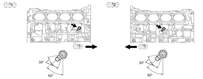
*1 for RH: *2 for LH: *3 Front - Torque:
- 30 N*m { 306 kgf*cm, 22 ft.*lbf }
Note
-
Do not rotate the drain cocks more than 1 revolution (360°) after tightening the drain cocks to the specified torque.
-
Do not loosen the drain cocks to adjust them. If an adjustment is necessary, remove the drain cocks and reinstall them.
-
Install the water drain cock plugs to the water drain cocks.
- Torque:
- 13 N*m { 133 kgf*cm, 10 ft.*lbf }
-
-
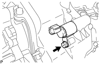
INSTALL CAMSHAFT TIMING OIL CONTROL VALVE ASSEMBLY
-
for Bank 1:
-
Apply a light coat of engine oil to a new O-ring.
-
Install the O-ring to the oil control valve.
-
Install the oil control valve with the bolt.
- Torque:
- 10 N*m { 102 kgf*cm, 7 ft.*lbf }
-
-
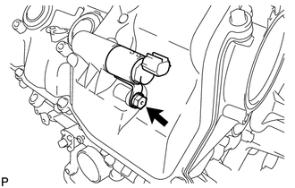
for Bank 2:
-
Apply a light coat of engine oil to a new O-ring.
-
Install the O-ring to the oil control valve.
-
Install the oil control valve with the bolt.
- Torque:
- 10 N*m { 102 kgf*cm, 7 ft.*lbf }
-
-
-
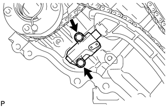
INSTALL CRANKSHAFT POSITION SENSOR
-
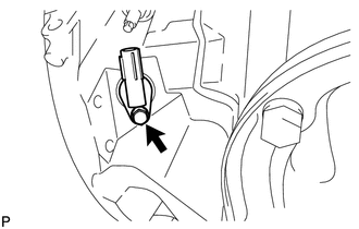
Install the crankshaft position sensor with the bolt.
- Torque:
- 10 N*m { 102 kgf*cm, 7 ft.*lbf }
-
-
INSTALL CAMSHAFT POSITION SENSOR
-
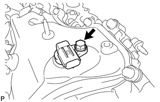
Install the camshaft position sensor with the bolt.
- Torque:
- 10 N*m { 102 kgf*cm, 7 ft.*lbf }
-
-
INSTALL VVT SENSOR
-
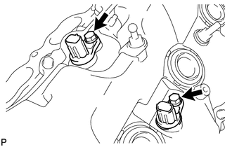
for Bank 1:
Install the 2 VVT sensors with the 2 bolts.
- Torque:
- 10 N*m { 102 kgf*cm, 7 ft.*lbf }
-
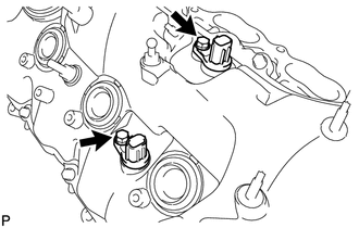
for Bank 2:
Install the 2 VVT sensors with the 2 bolts.
- Torque:
- 10 N*m { 102 kgf*cm, 7 ft.*lbf }
-
-
INSTALL SPARK PLUG
-
INSTALL OIL FILLER CAP HOUSING
-
Align the protrusion of a new gasket with the cutout of the oil filler cap housing, and install the gasket to the housing.
-
Install the cap housing with the 2 bolts.
- Torque:
- 10 N*m { 102 kgf*cm, 7 ft.*lbf }
-
-
INSTALL OIL FILLER CAP SUB-ASSEMBLY