ENGINE UNIT REMOVAL

CAUTION / NOTICE / HINT
Tech Tips
When viewed from the rear of the engine assembly, Bank 1 is on the left side and Bank 2 is on the right side.
PROCEDURE
-
REMOVE V-RIBBED BELT
-
REMOVE WITH MOTOR COMPRESSOR ASSEMBLY
-
REMOVE FRONT DIFFERENTIAL CARRIER ASSEMBLY
-
REMOVE ENGINE COVER SUB-ASSEMBLY LH
-
REMOVE NO. 6 COVER SUB-ASSEMBLY
-
REMOVE ENGINE COVER SUB-ASSEMBLY RH
-
REMOVE NO. 5 COVER SUB-ASSEMBLY
-
REMOVE ENGINE WIRE
-
Engine LH Side:
-
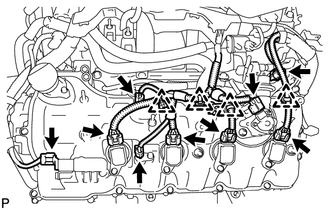
Disconnect the camshaft timing control valve connector.
-
Disconnect the 4 ignition coil connectors.
-
Disconnect the 2 VVT sensor connectors.
-
Disconnect the fuel pump connector (for high pressure).
-
Disconnect the fuel injector connector.
-
Disconnect the 4 clamps.
-
-
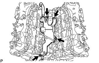
Engine Front Side:
-
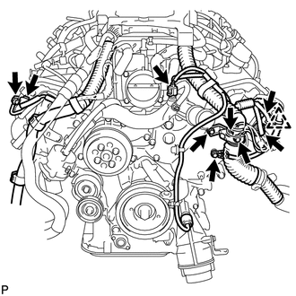
Disconnect the engine coolant temperature sensor connector.
-
Disconnect the 2 camshaft timing control motor connectors (for Bank 1).
-
Disconnect the 2 camshaft timing control motor connectors (for Bank 2).
-
Disconnect the clamp.
-
Remove the 3 bolts and disconnect the 3 ground wires.
-
-
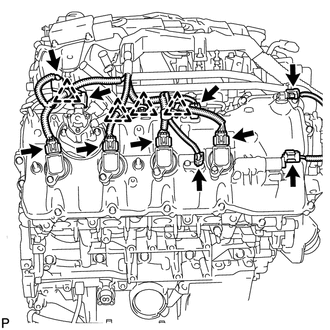
Engine RH Side:
-
Disconnect the camshaft timing control valve connector.
-
Disconnect the 4 ignition coil connectors.
-
Disconnect the 2 VVT sensor connectors.
-
Disconnect the fuel pump connector (for high pressure).
-
Disconnect the camshaft position sensor connector.
-
Disconnect the fuel injector connector.
-
Disconnect the 4 clamps.
-
-
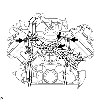
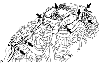
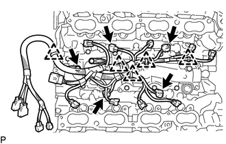
Engine Rear Side:
-
Disconnect the engine wire connector.
-
Disconnect the fuel relief valve connector.
-
Disconnect the 8 clamps.
-
Remove the 2 bolts and disconnect the 2 ground wires.
-
-
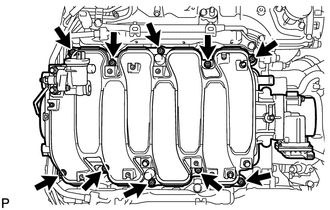
Engine Upper Side:
-
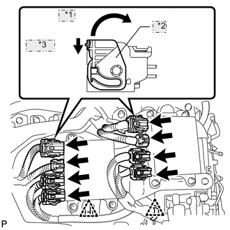
*1 Move *2 Lock Lever *3 Release Disconnect the 8 injector connectors as shown in the illustration.
-
Disconnect the 2 clamps.
-
Disconnect the purge VSV connector.
-
Disconnect the intake air control valve actuator connector.
-
Disconnect the 2 clamps and remove the 2 bolts and 2 clamp brackets.
-
Remove the 4 nuts and remove the engine wire.
-
-
-
REMOVE INJECTOR DRIVER
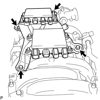
-
Remove the 2 bolts, 2 nuts and 2 injector drivers with bracket.
Note
Be careful not to drop or strike the injector driver.
-
-
REMOVE NO. 1 ENGINE COVER
-
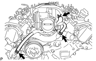
REMOVE PURGE VSV
-
Disconnect the purge line hose from the intake manifold.
-
Remove the bolt and purge VSV.
-
-
REMOVE HEATER WATER PUMP ASSEMBLY
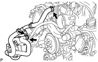
-
Slide the 2 clamps, and disconnect the 2 hoses from the water inlet housing and water by-pass pipe.
-
Remove the bolt and heater water pump.
-
-
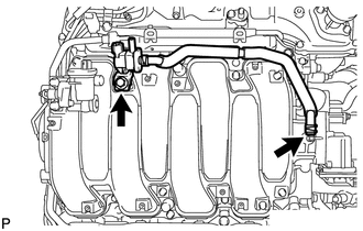
REMOVE WATER BY-PASS PIPE SUB-ASSEMBLY
-
Slide the clamp, and disconnect the water inlet hose from the front water by-pass joint.
-
Remove the 2 bolts and water by-pass pipe.
-
-
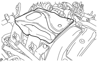
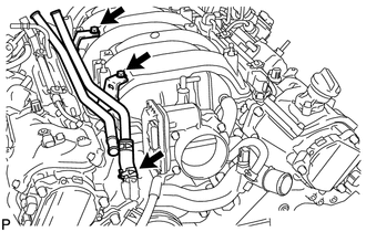
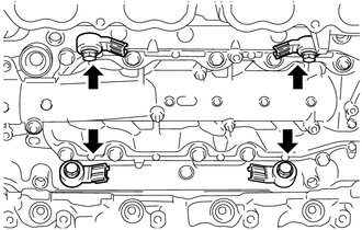
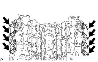
REMOVE INTAKE MANIFOLD ASSEMBLY
-
Disconnect the 2 water by-pass hoses and No. 1 ventilation hose as shown in the illustration.
-
Remove the 8 bolts, 2 nuts and intake manifold.
-
Remove the 2 gaskets from the intake manifold.
-
-
REMOVE FUEL TUBE SUB-ASSEMBLY
-
REMOVE FUEL PRESSURE PULSATION DAMPER ASSEMBLY
-
REMOVE NO. 3 FUEL PIPE SUB-ASSEMBLY
-
REMOVE NO. 2 FUEL PIPE SUB-ASSEMBLY
-
REMOVE FUEL PUMP ASSEMBLY (for Bank 1)
-
REMOVE FUEL PUMP ASSEMBLY (for Bank 2)
-
REMOVE WATER INLET HOUSING
-
REMOVE FUEL DELIVERY PIPE ASSEMBLY
-
REMOVE FUEL INJECTOR ASSEMBLY (for Port Injection)
-
REMOVE NO. 1 ENGINE COVER SUB-ASSEMBLY
-
REMOVE NO. 2 ENGINE COVER SUB-ASSEMBLY
-
REMOVE NO. 2 ENGINE COVER SUB-ASSEMBLY LH
-
REMOVE NO. 4 FUEL PIPE SUB-ASSEMBLY
-
REMOVE FUEL DELIVERY PIPE
-
REMOVE NO. 2 FUEL DELIVERY PIPE
-
REMOVE FUEL INJECTOR ASSEMBLY (for Direct Injection)
-
REMOVE FUEL INJECTOR SEAL
-
REMOVE SEPARATOR CASE
-
Remove the 4 bolts and separator case.
-
-
REMOVE ENGINE WIRE
-
Disconnect the 4 connectors and 5 clamps.
-
Remove the bolt and engine wire.
-
-
REMOVE KNOCK CONTROL SENSOR
-
Remove the 4 bolts and 4 knock control sensors.
-
-
REMOVE IGNITION COIL ASSEMBLY
-
Remove the 8 bolts and 8 ignition coils.
-