ENGINE ASSEMBLY INSTALLATION

CAUTION / NOTICE / HINT
CAUTION:
As the engine assembly with transmission is extremely heavy, the engine lifter may suddenly drop if the instructions listed in the repair manual are not followed. Therefore, always follow the instructions listed in the repair manual when performing this procedure.
PROCEDURE
-
INSTALL ENGINE HANGER
-
REMOVE ENGINE FROM ENGINE STAND
-
Lift the engine, and remove it from the engine stand.
Note
With the exception of installing the engine assembly to an engine stand or removing the engine assembly from an engine stand, do not perform any work on the engine while it is suspended, as doing so is dangerous.
-
Place the engine onto a waking bench.
-
-
INSTALL FLYWHEEL SUB-ASSEMBLY
-
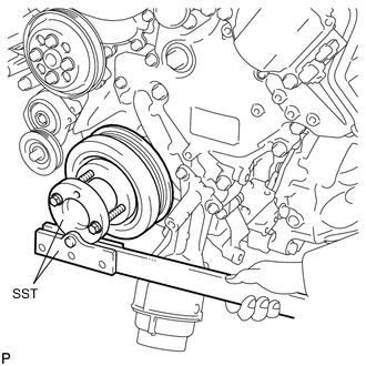
Using SST, hold the crankshaft.
- SST
- 09213-54015 ( 90119-08216 )
- 09330-00021
-
Clean the bolts and their installation holes.
-
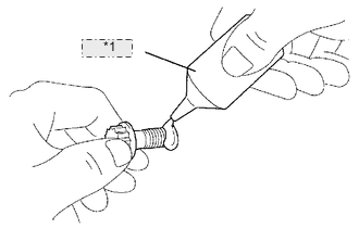
*1 Adhesive Apply adhesive to 2 or 3 threads of the bolt end.
Adhesive Toyota Genuine Adhesive 1324, Three Bond 1324 or equivalent -
Install the crankshaft angle sensor plate and flywheel sub-assembly on the crankshaft.
-
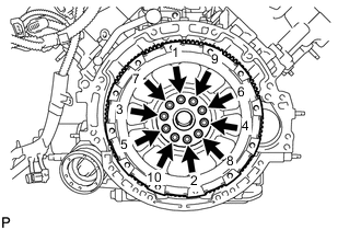
Uniformly install and tighten the 10 bolts in the sequence shown in the illustration.
- Torque:
- 30 N*m { 301 kgf*cm, 22 ft.*lbf }
Note
Do not strike or damage the flywheel sub-assembly installation bolts. Be sure to handle them carefully.
-
Mark the upside of each flywheel sub-assembly installation bolt with paint.
-
Tighten the flywheel sub-assembly installation bolts 90°.
-
Check that the painted marks are now at a 90° angle to the upside.
Note
Do not start the engine for at least 1 hour after the installation.
-
-
INSTALL INPUT TRANSMISSION DAMPER COVER ASSEMBLY
-
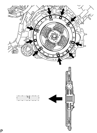
*1 Flywheel Side Install the input transmission damper cover assembly with the 9 bolts.
- Torque:
- 49 N*m { 500 kgf*cm, 36 ft.*lbf }
Note
Make sure to insert the clutch disc in the correct direction.
-
-
INSTALL HYBRID VEHICLE TRANSMISSION ASSEMBLY
-
INSTALL STARTER HOLE INSULATOR
-
INSTALL OUTLET NO. 1 HYBRID WATER PUMP PIPE (for LHD)
-
Install the outlet No. 1 hybrid water pump pipe with the 2 bolts.
- Torque:
- 22 N*m { 224 kgf*cm, 16 ft.*lbf }
-
-
INSTALL OIL COOLER TUBE SUB-ASSEMBLY
-
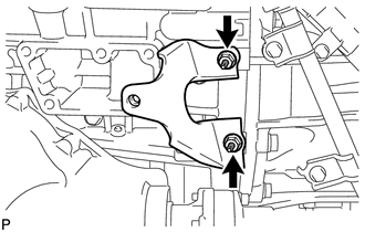
INSTALL REAR NO. 2 ENGINE MOUNTING INSULATOR
Tech Tips
Only perform this procedure when replacement of the rear No. 2 engine mounting insulator is necessary.
-
Install the rear No. 2 engine mounting insulator with the 2 bolts.
- Torque:
- 30 N*m { 306 kgf*cm, 22 ft.*lbf }
-
-
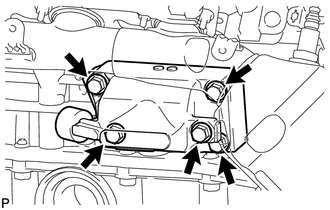
INSTALL REAR NO. 1 ENGINE MOUNTING INSULATOR
Tech Tips
Only perform this procedure when replacement of the rear No. 1 engine mounting insulator is necessary.
-
Install the 2 rear No. 1 engine mounting insulators with the 4 bolts.
- Torque:
- 30 N*m { 306 kgf*cm, 22 ft.*lbf }
-
-
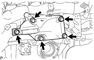
INSTALL REAR ENGINE MOUNTING MEMBER
Tech Tips
Only perform this procedure when replacement of the rear engine mounting member is necessary.
-
Install the rear engine mounting member and No. 3 mounting insulator with the 5 nuts.
- Torque:
- 38 N*m { 387 kgf*cm, 28 ft.*lbf }
-
-
INSTALL FRONT PROPELLER SHAFT ASSEMBLY
-
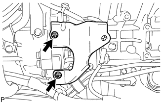
INSTALL FRONT NO. 2 ENGINE MOUNTING BRACKET LH
-
Temporarily install the front No. 2 engine mounting bracket LH with the 2 nuts.
-
Temporarily install the front No. 1 engine mounting bracket LH with the 5 bolts.
-
Tighten the 2 nuts.
- Torque:
- 21 N*m { 214 kgf*cm, 15 ft.*lbf }
-
Remove the 5 bolts and front No. 1 engine mounting bracket LH.
-
-
INSTALL FRONT NO. 2 ENGINE MOUNTING BRACKET RH
-
Temporarily install the front No. 2 engine mounting bracket RH with the 2 nuts.
-
Temporarily install the front No. 1 engine mounting bracket RH with the 5 bolts.
-
Tighten the 2 nuts.
- Torque:
- 21 N*m { 214 kgf*cm, 15 ft.*lbf }
-
Remove the 5 bolts and front No. 1 engine mounting bracket RH.
-
-
INSTALL EXHAUST MANIFOLD SUB-ASSEMBLY LH
-
INSTALL EXHAUST MANIFOLD SUB-ASSEMBLY RH
-
INSTALL FRONT NO. 1 ENGINE MOUNTING BRACKET LH
-
Install the front No. 1 engine mounting bracket LH with the 5 bolts.
- Torque:
- 35 N*m { 357 kgf*cm, 26 ft.*lbf }
-
-
INSTALL FRONT NO. 1 ENGINE MOUNTING BRACKET RH
-
Install the front No. 1 engine mounting bracket RH with the 5 bolts.
- Torque:
- 35 N*m { 357 kgf*cm, 26 ft.*lbf }
-
-
INSTALL FRONT ENGINE MOUNTING INSULATOR
-
Install the 2 spacers and 2 front engine mounting insulators with the 2 nuts.
- Torque:
- 35 N*m { 357 kgf*cm, 26 ft.*lbf }
-
-
INSTALL NO. 2 EXHAUST MANIFOLD HEAT INSULATOR
-
INSTALL NO. 1 EXHAUST MANIFOLD HEAT INSULATOR
-
INSTALL ENGINE OIL LEVEL DIPSTICK GUIDE
-
Apply a light coat of engine oil to a new O-ring.
-
Install the O-ring to the engine oil level dipstick guide.
-
Install the engine oil level dipstick guide with the bolt.
- Torque:
- 10 N*m { 102 kgf*cm, 7 ft.*lbf }
-
Install the engine oil level dipstick.
-
-
INSTALL FRONT FRAME ASSEMBLY
-
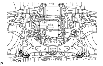
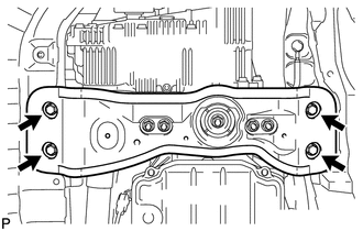
Slowly lower the engine and set it to the front frame assembly.
-
Install the 4 nuts.
- Torque:
- 70 N*m { 714 kgf*cm, 52 ft.*lbf }
-
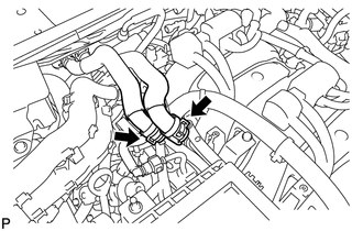
Attach the 2 clips and connect the heater wire connector.
-
-
INSTALL ENGINE AND TRANSMISSION
-
Place the engine on a engine lifter.
Note
-
Place wooden blocks or plate lift attachments so that the engine is level.
-
With the exception of installing the engine assembly to an engine stand or removing the engine assembly from an engine stand, do not perform any work on the engine while it is suspended, as doing so is dangerous.
-
Never install attachments to the oil pan of the engine assembly or transmission as doing so may deform the oil pan.
-
-
Remove the 2 bolts and 2 engine hangers.
-
Operate the engine lifter, then install the engine to the vehicle.
Note
Make sure that the engine is clear of all wiring and hoses.
-
Align the front frame to the marks on the vehicle, and temporarily install the front frame with the 4 bolts.
Note
Make sure the crossmember is aligned to the vehicle marks as accurately as possible. If not performed accurately, the suspension alignment may become extremely misaligned.
-
Install the 4 rear engine mounting member's bolts.
- Torque:
- 35 N*m { 354 kgf*cm, 26 ft.*lbf }
-
Tighten the 4 front frame bolts.
- Torque:
- 165 N*m { 1683 kgf*cm, 122 ft.*lbf }
-
-
CONNECT FRONT LOWER SHOCK ABSORBER BRACKET SUB-ASSEMBLY LH
-
Connect the front lower shock absorber bracket sub-assembly LH. Then install the bolt.
- Torque:
- 48 N*m { 489 kgf*cm, 35 ft.*lbf }
-
-
CONNECT FRONT LOWER SHOCK ABSORBER BRACKET SUB-ASSEMBLY RH
-
Connect the front lower shock absorber bracket sub-assembly RH. Then install the bolt.
- Torque:
- 48 N*m { 489 kgf*cm, 35 ft.*lbf }
-
-
CONNECT TRANSMISSION CONTROL SHAFT LEVER
-
Connect the transmission control shaft lever and spring washer with the nut.
- Torque:
- 16 N*m { 163 kgf*cm, 12 ft.*lbf }
-
-
INSTALL PROPELLER SHAFT WITH CENTER BEARING ASSEMBLY
-
INSTALL FRONT EXHAUST PIPE ASSEMBLY
-
INSTALL FRONT DRIVE SHAFT ASSEMBLY
-
INSTALL NO. 2 STEERING INTERMEDIATE SHAFT ASSEMBLY
-
INSTALL NO. 2 AIR DUCT SUB-ASSEMBLY (for LHD)
-
Attach the 2 claws to install the No. 2 air duct sub-assembly with the bolt.
- Torque:
- 9.8 N*m { 100 kgf*cm, 87 in.*lbf }
-
-
INSTALL NO. 1 AIR DUCT SUB-ASSEMBLY (for RHD)
-
Attach the 2 claws to install the No. 1 air duct sub-assembly with the bolt.
- Torque:
- 9.8 N*m { 100 kgf*cm, 87 in.*lbf }
-
-
INSTALL DRIVER SIDE KNEE AIRBAG ASSEMBLY
-
CONNECT HOSES AND CONNECTORS
-
for LHD:
-
Connect the 2 heater hoses.
-
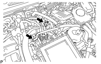
Connect the purge line hose and No. 5 inverter cooling hose.
-
Connect the heater wire connector.
-
-
for RHD:
-
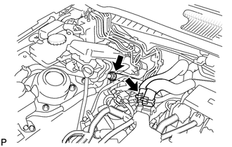
Connect the 2 heater hoses and No. 6 inverter cooling hose.
-
Connect the purge line hose and No. 2 inverter cooling hose.
-
Connect the heater wire connector.
-
-
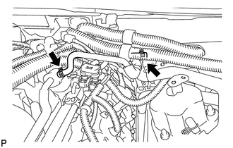
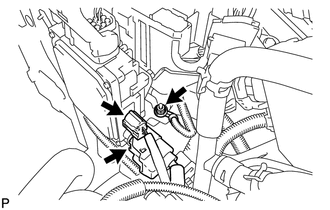
Attach the 5 clamps and connect the 2 connectors.
-
Install the heater water pump and bracket with the 2 nuts.
- Torque:
- 9.8 N*m { 100 kgf*cm, 87 in.*lbf }
-
Connect the heater water pump connector.
-
Install the inverter cooling pipe bracket with the nut. Then attach the 2 clamps.
- Torque:
- 13 N*m { 133 kgf*cm, 10 ft.*lbf }
-
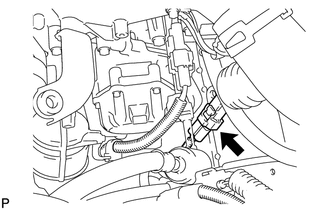
Connect the 2 oil pump motor controller connectors.
Tech Tips
Refer to the following procedures to connect the oil pump driver connector Click here.
-
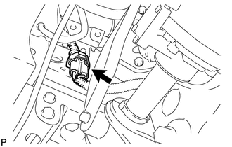
Install the ground wire with the nut.
- Torque:
- 8.5 N*m { 87 kgf*cm, 75 in.*lbf }
-
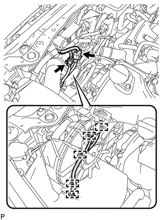
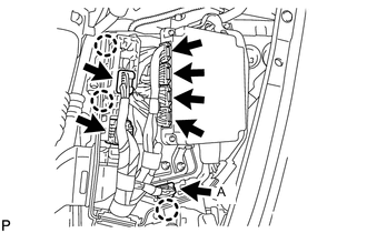
Connect the 3 connectors to the front controller and attach the clamp.
-
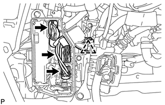
Lift up the wiring harness support and connect the 4 ECM connectors.
-
Install the wiring harness support to the ECM box.
-
Attach the clip of connector A to the ECM box.
-
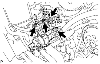
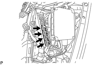
Connect the 4 hybrid vehicle control ECU connectors and 2 wiring harness support connectors.
-
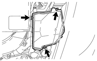
Install the engine room ECU box cover with the 3 bolts.
- Torque:
- 5.5 N*m { 56 kgf*cm, 49 in.*lbf }
-
-
INSTALL WATER PUMP ASSEMBLY WITH MOTOR AND BRACKET
-
CONNECT SUCTION HOSE SUB-ASSEMBLY
-
Remove the vinyl tape and/or plastic bags from the openings of the disconnected parts and motor compressor.
-
Sufficiently apply compressor oil to a new O-ring and the fitting surface of the motor compressor.
Compressor oil ND-OIL 11 or equivalent -
Install the O-ring on the suction hose sub-assembly.
-
Connect the suction hose sub-assembly to the motor compressor with the bolt.
- Torque:
- 9.8 N*m { 100 kgf*cm, 87 in.*lbf }
-
-
CONNECT DISCHARGE HOSE SUB-ASSEMBLY
-
Remove the vinyl tape and/or plastic bags from the openings of the disconnected parts and motor compressor.
-
Sufficiently apply compressor oil to a new O-ring and the fitting surface of the motor compressor.
Compressor oil ND-OIL 11 or equivalent -
Install the O-ring on the discharge hose sub-assembly.
-
Connect the discharge hose sub-assembly to the motor compressor with the bolt.
- Torque:
- 9.8 N*m { 100 kgf*cm, 87 in.*lbf }
-
-
CONNECT GENERATOR CABLE (for LHD)
-
CONNECT MOTOR CABLE (for LHD)
-
INSTALL INVERTER TERMINAL COVER (for LHD)
-
CONNECT GENERATOR CABLE (for RHD)
-
CONNECT MOTOR CABLE (for RHD)
-
INSTALL INVERTER TERMINAL COVER (for RHD)
-
CONNECT NO. 3 FUEL HOSE
-
CONNECT NO. 1 FUEL HOSE
-
INSTALL ENGINE OIL PRESSURE SWITCH ASSEMBLY
-
INSTALL RESONATOR BRACKET SUB-ASSEMBLY
-
INSTALL NO. 2 RADIATOR HOSE
-
INSTALL NO. 1 RADIATOR HOSE
-
INSTALL OUTLET ENGINE ROOM ECM DUCT
-
Install the outlet engine room ECM duct.
-
-
INSTALL RADIATOR RESERVOIR ASSEMBLY
-
INSTALL AIR CLEANER ASSEMBLY RH
-
INSTALL AIR CLEANER ASSEMBLY LH
-
INSTALL INTAKE AIR CONNECTOR PIPE
-
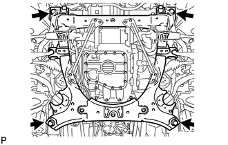
INSTALL REAR FRAME SIDE RAIL
-
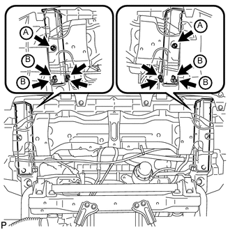
Install the 2 rear frame side rails with the 6 bolts and 4 nuts.
- Torque:
- for bolt A
- 30 N*m { 306 kgf*cm, 22 ft.*lbf }
- for nut B
- 44 N*m { 453 kgf*cm, 33 ft.*lbf }
-
-
CONNECT FRONT ACTIVE STABILIZER CONTROL ACTUATOR CONNECTOR (w/ Active Stabilizer System)
-
INSTALL INLET ENGINE ROOM ECM DUCT (w/ Active Stabilizer System)
-
INSTALL NO. 3 COOL AIR INTAKE DUCT SUB-ASSEMBLY (w/ Active Stabilizer System)
-
CONNECT FRONT FENDER LINER LH (w/ Active Stabilizer System)
-
INSTALL FRONT BUMPER COVER
-
CONNECT OUTLET OIL COOLER HOSE
-
CONNECT INLET OIL COOLER HOSE
-
ADD FRONT DIFFERENTIAL OIL
-
ADD ENGINE COOLANT
-
ADD ENGINE OIL
-
INSTALL SERVICE PLUG GRIP
-
CONNECT CABLE TO NEGATIVE AUXILIARY BATTERY TERMINAL
Note
When disconnecting the cable, some systems need to be initialized after the cable is reconnected Click here.
-
ADD COOLANT (for Inverter)
-
INSPECT FOR COOLANT LEAK (for Inverter)
-
CHARGE REFRIGERANT
-
CHECK TRANSMISSION FLUID LEVEL
-
INSPECT FOR SHIFT LEVER POSITION
-
INSPECT FOR OIL LEAK
-
INSPECT FOR COOLANT LEAK
-
INSPECT FOR FUEL LEAK
-
INSPECT FOR REFRIGERANT LEAK
-
INSPECT FOR EXHAUST GAS LEAK
-
INSPECT IGNITION TIMING
-
INSPECT ENGINE IDLE SPEED
-
INSPECT CO/HC
-
PLACE FRONT WHEELS FACING STRAIGHT AHEAD
-
CHECK AND ADJUST FRONT WHEEL ALIGNMENT
-
MEASURE VEHICLE HEIGHT
-
ADJUST OBJECT RECOGNITION CAMERA
-
INSTALL FRONT LOWER SUSPENSION MEMBER PROTECTOR
-
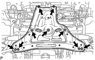
Install the front lower suspension member protector with the 9 bolts.
- Torque:
- for bolt A
- 20 N*m { 204 kgf*cm, 15 ft.*lbf }
- except bolt A
- 58 N*m { 593 kgf*cm, 43 ft.*lbf }
-
-
INSTALL NO. 1 ENGINE UNDER COVER
-
INSTALL FRONT WHEEL OPENING EXTENSION PAD LH
-
INSTALL FRONT WHEEL OPENING EXTENSION PAD RH
-
INSTALL NO. 2 ENGINE UNDER COVER
-
Install the No. 2 engine under cover with the 4 screws and 2 clips.
-
-
INSTALL FRONT CENTER FLOOR COVER (w/ Cover)
-
Install the front center floor cover with the 3 screws, 2 bolts and clip.
- Torque:
- 5.4 N*m { 55 kgf*cm, 48 in.*lbf }
-
-
INSTALL INVERTER COVER ASSEMBLY LH (for RHD)
-
Install the inverter cover assembly LH and attach the 2 clips.
-
-
INSTALL INVERTER COVER ASSEMBLY RH (for LHD)
-
Install the inverter cover assembly RH and attach the 2 clips.
-
-
INSTALL MOTOR CABLE COVER LH (for RHD)
-
Install the motor cable cover LH with the 2 clips.
-
-
INSTALL MOTOR CABLE COVER RH (for LHD)
-
Install the motor cable cover RH with the 2 clips.
-
-
INSTALL COWL TOP VENTILATOR LOUVER RH (for LHD)
-
INSTALL COWL TOP VENTILATOR LOUVER LH (for RHD)
Tech Tips
Use the same procedures described for LHD vehicles.
-
INSTALL ENGINE ROOM SIDE COVER LH
-
INSTALL ENGINE ROOM SIDE COVER RH
-
CHECK ENGINE COOLANT LEVEL
-
INSTALL NO. 1 AIR CLEANER INLET
-
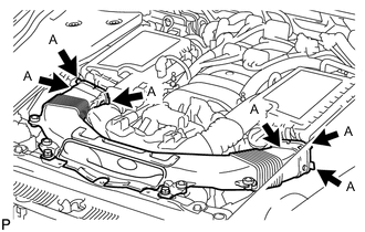
Align the holes with the connection areas labeled A, and attach the No. 1 air cleaner inlet.
-
Install the No. 1 air cleaner inlet with the 2 bolts.
- Torque:
- 5.0 N*m { 51 kgf*cm, 44 in.*lbf }
-
-
INSTALL AIR CLEANER INLET COVER SUB-ASSEMBLY
-
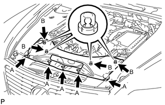
Attach the 4 clips labeled B.
Note
-
Make sure the clips are attached securely.
-
Attaching the clips forcefully or hitting the top of the clips may damage them.
-
-
Install the air cleaner inlet cover sub-assembly with the 5 clips labeled A.
-
-
INSTALL V-BANK COVER SUB-ASSEMBLY
-
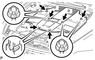
After sliding the V-bank cover sub-assembly from the vehicle front to the rear to attach the 2 clips labeled A, attach the 4 clips labeled B and install the V-bank cover sub-assembly.
CAUTION:
-
Make sure the clips are attached securely.
-
Attaching the clips forcefully or hitting the top of the clips may damage them.
-
-
-
INSTALL BATTERY SERVICE HOLE COVER LH
-
INSTALL DECK TRIM SIDE BOARD LH (w/o Spare Tire)
-
INSTALL DECK BOARD ASSEMBLY (w/o Spare Tire)
-
INSTALL LUGGAGE COMPARTMENT MAT SUB-ASSEMBLY (w/ Spare Tire)