CYLINDER BLOCK INSPECTION

CAUTION / NOTICE / HINT
Tech Tips
When viewed from the rear of the engine assembly, Bank 1 is on the left side and Bank 2 is on the right side.
PROCEDURE
-
INSPECT NO. 1 OIL NOZZLE SUB-ASSEMBLY
-
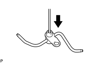
Push the check valve with a pin to check if it is stuck.
If stuck, replace the No. 1 oil nozzle sub-assembly.
-
Push the check valve with a pin to check if it moves smoothly.
If it does not move smoothly, clean or replace the No. 1 oil nozzle sub-assembly.
-
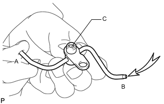
While covering A, apply air into B. Check that air does not leak through C. Perform the check again while covering B and applying air into A.
If air leaks, clean or replace the No. 1 oil nozzle sub-assembly.
-
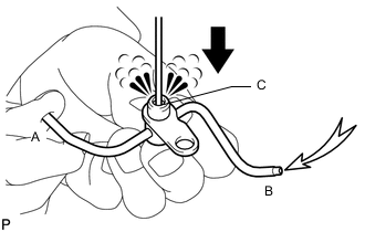
Push the check valve while covering A, and apply air into B. Check that air passes through C. Perform the check again while covering B, pushing the check valve and applying air into A.
If air does not pass through C, clean or replace the No. 1 oil nozzle sub-assembly.
-
-
CHECK CYLINDER BLOCK SUB-ASSEMBLY
-
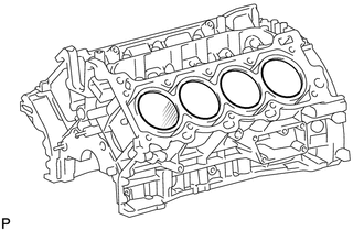
Visually check the cylinder for vertical scratches.
If necessary, replace the cylinder block.
-
-
INSPECT CYLINDER BLOCK FOR WARPAGE
-
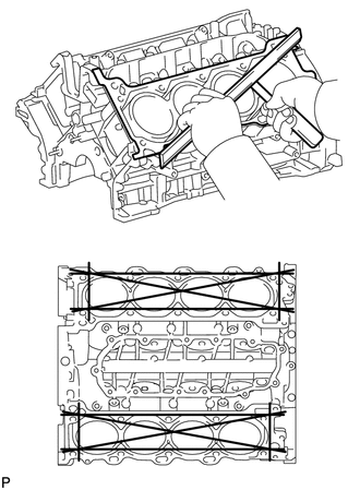
Using a precision straightedge and feeler gauge, measure the warpage of the surfaces where the cylinder head gaskets contact the cylinder block.
Maximum warpage 0.05 mm (0.00197 in.) If the warpage is greater than the maximum, replace the cylinder block.
-
-
INSPECT CYLINDER BORE
-
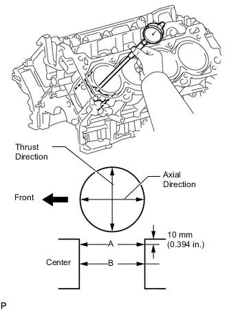
Using a cylinder gauge, measure the cylinder bore diameter at positions A and B in the thrust and axial directions.
Standard diameter 94.000 to 94.012 mm (3.700 to 3.701 in.) Maximum diameter 94.200 mm (3.709 in.) If the diameter is greater than the maximum, replace the cylinder block.
-
-
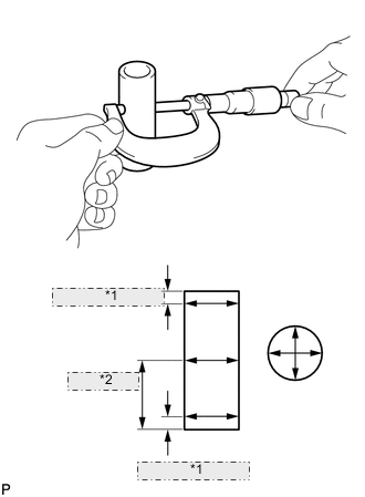
INSPECT PISTON SUB-ASSEMBLY WITH PIN
-
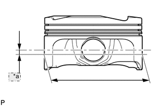
*a 5 mm Using a micrometer, measure the piston diameter at a position that is 5 mm (0.197 in.) below the center of the piston pin hole (refer to the illustration).
Standard diameter 93.980 to 93.990 mm (3.7000 to 3.7004 in.) Minimum diameter 93.830 mm (3.6941 in.) If the diameter is less than the minimum, replace the piston sub-assembly with pin.
-
-
INSPECT PISTON OIL CLEARANCE
-
Measure the cylinder bore diameter in the thrust direction.
-
Subtract the piston diameter measurement from the cylinder bore diameter measurement.
Standard oil clearance 0.035 to 0.057 mm (0.00138 to 0.00224 in.) Maximum oil clearance 0.370 mm (0.0146 in.) If the oil clearance is greater than the maximum, replace all the pistons. If necessary, replace the cylinder block.
-
-
INSPECT RING GROOVE CLEARANCE
-
Using a feeler gauge, measure the clearance between a new piston ring and the wall of the ring groove.
Standard ring groove clearance Item Specified Condition No. 1 0.020 to 0.070 mm (0.000787 to 0.00276 in.) No. 2 0.020 to 0.060 mm (0.000787 to 0.00236 in.) Oil 0.020 to 0.070 mm (0.000787 to 0.00276 in.) If the clearance is not as specified, replace the piston.
-
-
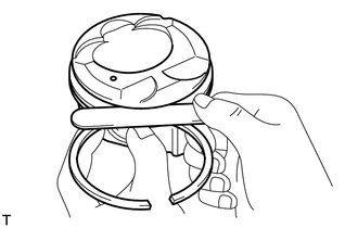
INSPECT PISTON RING END GAP
-
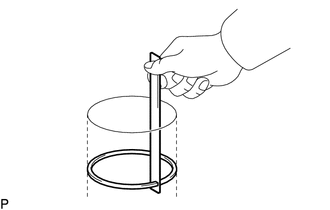
Insert the piston ring into the cylinder bore.
-
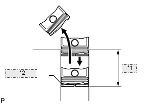
*1 60 mm *2 Piston Ring Using a piston, push the piston ring a little beyond the bottom of the ring travel, 60 mm (2.36 in.) from the top of the cylinder block.
-
Using a feeler gauge, measure the end gap.
Standard end gap Item Specified Condition No. 1 0.23 to 0.28 mm (0.00905 to 0.0110 in.) No. 2 0.35 to 0.45 mm (0.0138 to 0.0177 in.) Oil 0.10 to 0.20 mm (0.00394 to 0.00787 in.) Maximum end gap Item Specified Condition No. 1 0.40 mm (0.0157 in.) No. 2 0.50 mm (0.0197 in.) Oil 0.45 mm (0.0177 in.) If the end gap is greater than the maximum, replace the piston ring. If the end gap is greater than the maximum even with a new piston ring, replace the cylinder block.
-
-
INSPECT PISTON PIN OIL CLEARANCE
Tech Tips
There is only 1 type of supply part for piston sub-assembly with pin.
-
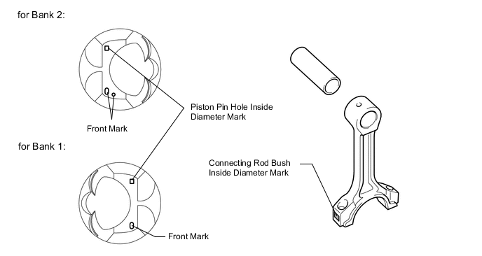
Check each mark on the piston, piston pin and connecting rod.
-
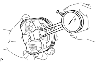
Using a caliper gauge, measure the inside diameter of the piston pin hole.
Tech Tips
Measure the diameter 5 mm (0.197 in.) inward from the snap ring groove.
Standard piston pin hole inside diameter Mark Specified Condition A 21.998 to 22.001 mm (0.86606 to 0.86618 in.) B 22.002 to 22.004 mm (0.86622 to 0.86630 in.) C 22.005 to 22.007 mm (0.86634 to 0.86642 in.) -
*1 5 mm (0.197 in.) *2 28 mm (1.10 in.) Using a micrometer, measure the piston pin diameter.
Standard piston pin diameter Mark Specified Condition A 21.997 to 22.000 mm (0.86602 to 0.86614 in.) B 22.001 to 22.003 mm (0.86618 to 0.86626 in.) C 22.004 to 22.006 mm (0.86630 to 0.86638 in.) -
Subtract the piston pin diameter measurement from the piston pin hole diameter measurement.
Standard oil clearance -0.002 to 0.004 mm (-0.0000787 to 0.000157 in.) Maximum oil clearance 0.015 mm (0.000591 in.) If the oil clearance is greater than the maximum, replace the piston and piston pin as a set.
-
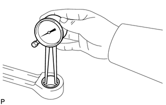
Using a caliper gauge, measure the inside diameter of the connecting rod bush.
Standard bush inside diameter Mark Specified Condition A 22.005 to 22.008 mm (0.86633 to 0.86646 in.) B 22.009 to 22.011 mm (0.86650 to 0.86657 in.) C 22.012 to 22.014 mm (0.86661 to 0.86669 in.) -
Subtract the piston pin diameter measurement from the bush inside diameter measurement.
Standard oil clearance 0.005 to 0.011 mm (0.000197 to 0.000433 in.) Maximum oil clearance 0.03 mm (0.00118 in.) If the oil clearance is greater than the maximum, replace the bush. If necessary, replace the connecting rod and piston pin as a set.
-
-
INSPECT CONNECTING ROD SUB-ASSEMBLY
-
Using a rod aligner and feeler gauge, check the connecting rod alignment.
-
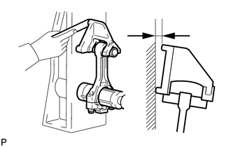
Check for bend.
Maximum bend 0.05 mm (0.00197 in.) per 100 mm (3.94 in.) If the bend is greater than the maximum, replace the connecting rod.
-
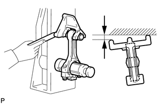
Check for twist.
Maximum twist 0.15 mm (0.00591 in.) per 100 mm (3.94 in.) If the twist is greater than the maximum, replace the connecting rod.
-
-
-
INSPECT CONNECTING ROD BOLT
-
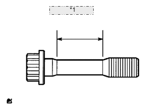
*1 Measuring Point Using a vernier caliper, measure the tension portion diameter of the bolt.
Standard diameter 8.5 to 8.6 mm (0.335 to 0.339 in.) Minimum diameter 8.3 mm (0.327 in.) If the diameter is less than the minimum, replace the bolt.
-
-
INSPECT CRANKSHAFT
-
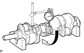
Inspect for circle runout.
-
Place the crankshaft on V-blocks.
-
Using a dial indicator, measure the circle runout at the center journal.
Maximum circle runout 0.01 mm (0.000394 in.) If the circle runout is greater than the maximum, replace the crankshaft.
-
-
Inspect the main journals.
-
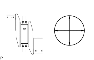
Using a micrometer, measure the diameter of each main journal.
Standard journal diameter 66.988 to 67.000 mm (2.6373 to 2.6378 in.) If the diameter is not as specified, check the oil clearance. If necessary, replace the crankshaft.
-
Check each main journal for taper and out-of-round as shown in the illustration.
Maximum taper and out-of-round 0.003 mm (0.000118 in.) If the taper and out-of-round is greater than the maximum, replace the crankshaft.
-
-
Inspect the crank pin.
-
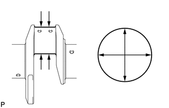
Using a micrometer, measure the diameter of each crank pin.
Standard crank pin diameter 52.982 to 53.000 mm (2.086 to 2.087 in.) If the diameter is not as specified, check the oil clearance. If necessary, replace the crankshaft.
-
Check each crank pin for taper and out-of-round as shown in the illustration.
Maximum taper and out-of-round 0.003 mm (0.000118 in.) If the taper and out-of-round is greater than the maximum, replace the crankshaft.
-
-
-
INSPECT CRANKSHAFT OIL CLEARANCE
-
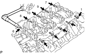
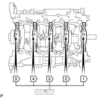
Uniformly loosen and remove the 10 bearing cap bolts and 10 seal washers in several steps, in the sequence shown in the illustration.
-
Uniformly loosen the 20 bearing cap bolts in several steps, in the sequence shown in the illustration.
-
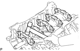
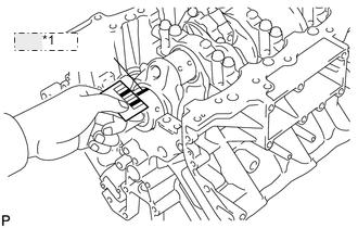
Using a screwdriver, slightly pry up the 5 crankshaft bearing caps.
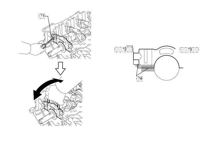
*1 Protective Tape *2 Cylinder Block *3 Bearing Cap *4 Joint Surface Note
-
Be careful not to damage the joint surface of the cylinder block and crankshaft bearing caps.
-
Pry up the left and right side of the cap little by little.
Tech Tips
Tape the screwdriver tip before use.
-
-
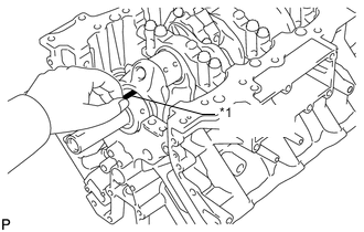
Using 2 inside position crankshaft bearing cap bolts, loosen each crankshaft bearing cap by moving it forward and backward, and remove each crankshaft bearing cap.
-
Clean each main journal and bearing.
-
Check each main journal and bearing for pitting and scratches.
If the journal or bearing is damaged, replace the bearing.
-
Place the crankshaft on the cylinder block.
-
*1 Plastigage Lay a strip of Plastigage across each journal.
-
*1 Number Mark Examine the front marks and numbers, and install the crankshaft bearing caps on the cylinder block.
Tech Tips
A number is marked on each crankshaft bearing cap to indicate the installation position.
-
Apply a light coat of engine oil the threads and under the heads of the bearing cap bolts.
-
Temporarily install the 10 crankshaft bearing cap bolts to the inside positions.
-

*1 91 mm *2 Less than 6 mm Push the crankshaft bearing cap by hand until the clearance between the crankshaft bearing cap and cylinder block is less than 6 mm (0.236 in.).
Bolt length 91 mm (3.58 in.) -
Using a plastic-faced hammer, lightly tap the bearing cap to ensure a proper fit.
-
Apply a light coat of engine oil to the threads and under the heads of the 10 crankshaft bearing cap bolts.
-
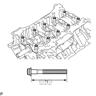
*1 79.5 mm Temporarily install the 10 crankshaft bearing cap bolts to the outside positions.
Bolt length 79.5 mm (3.13 in.) Tech Tips
The crankshaft bearing cap bolts are tightened in 2 progressive steps.
-
Step 1:
-
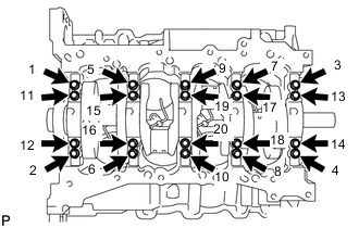
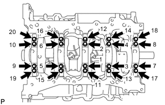
Uniformly tighten the 20 crankshaft bearing cap bolts in the sequence shown in the illustration.
- Torque:
- for inside position
- 61 N*m { 622 kgf*cm, 45 ft.*lbf }
- for outside position
- 27 N*m { 275 kgf*cm, 20 ft.*lbf }
If a crankshaft bearing cap bolt does not meet the specified torque, replace it.
Note
Do not turn the crankshaft.
-
-
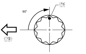
*1 Painted Mark *2 Front Step 2:
-
Mark the front of the bearing cap bolts with paint.
-
Tighten the bearing cap bolts 90° in the order shown in step 1.
-
Check that the painted marks are now at a 90° angle to the front.
-
-
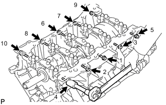
Install and uniformly tighten the 10 crankshaft bearing cap bolts and 10 seal washers in several steps, in the sequence shown in the illustration.
- Torque:
- 45 N*m { 459 kgf*cm, 33 ft.*lbf }
-
Remove the 30 bolts and bearing caps.
-
*1 Plastigage Measure the Plastigage at its widest point.
Standard oil clearance Number Mark Specified Condition No. 1 and No. 5 journal 0.017 to 0.030 mm (0.000669 to 0.00118 in.) Other journals 0.024 to 0.037 mm (0.000945 to 0.00146 in.) Maximum oil clearance Number Mark Specified Condition No. 1 and No. 5 journal 0.050 mm (0.00197 in.) Other journals 0.060 mm (0.00236 in.) If the oil clearance is greater than the maximum, perform the next step. If necessary, replace the crankshaft.
Tech Tips
After measurement, completely remove the Plastigage.
-
Replace the crankshaft bearing.
-
Replace the bearing with one having the same number.
Tech Tips
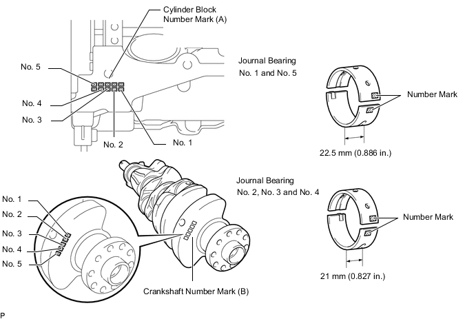
If replacing a bearing, replace it with one having the same number. If the number of the bearing cannot be determined, select the correct bearing by adding together the numbers imprinted on the cylinder block and crankshaft. Refer to the table below for the appropriate bearing number. There are 6 sizes of standard bearings. For No. 1 and No. 5 position bearings, use bearings marked 4, 5, 6, 7, 8 and 9. For other position bearings, use bearing marked 3, 4, 5, 6, 7 and 8.
-
Example:
Cylinder block "07" + Crankshaft "06" = Total number 13 (Use upper bearing "6" and lower bearing "7")
-
A = Cylinder block number mark
-
B = Crankshaft number mark
Standard crankshaft main journal diameter Number Mark Specified Condition 00 66.999 to 67.000 mm (2.63776 to 2.63780 in.) 01 66.998 to 66.999 mm (2.63772 to 2.63776 in.) 02 66.997 to 66.998 mm (2.63768 to 2.63772 in.) 03 66.996 to 66.997 mm (2.63764 to 2.63768 in.) 04 66.995 to 66.996 mm (2.63760 to 2.63764 in.) 05 66.994 to 66.995 mm (2.63756 to 2.63760 in.) 06 66.993 to 66.994 mm (2.63752 to 2.63756 in.) 07 66.992 to 66.993 mm (2.63748 to 2.63752 in.) 08 66.991 to 66.992 mm (2.63744 to 2.63748 in.) 09 66.990 to 66.991 mm (2.63740 to 2.63744 in.) 10 66.989 to 66.990 mm (2.63736 to 2.63740 in.) 11 66.988 to 66.989 mm (2.63732 to 2.63736 in.) Standard bearing center wall thickness No. 1 and No. 5 journal (A) + (B) Upper Bearing Lower Bearing Number Mark Specified Condition Number Mark Specified Condition 00 to 02 4 2.501 to 2.504 mm (0.09846 to 0.09858 in.) 5 2.488 to 2.491 mm (0.09795 to 0.09807 in.) 03 to 05 5 2.504 to 2.507 mm (0.09858 to 0.09870 in.) 5 2.488 to 2.491 mm (0.09795 to 0.09807 in.) 06 to 08 5 2.504 to 2.507 mm (0.09858 to 0.09870 in.) 6 2.491 to 2.494 mm (0.09807 to 0.09819 in.) 09 to 11 6 2.507 to 2.510 mm (0.09870 to 0.09882 in.) 6 2.491 to 2.494 mm (0.09807 to 0.09819 in.) 12 to 14 6 2.507 to 2.510 mm (0.09870 to 0.09882 in.) 7 2.494 to 2.497 mm (0.09819 to 0.09831 in.) 15 to 17 7 2.510 to 2.513 mm (0.09882 to 0.09894 in.) 7 2.494 to 2.497 mm (0.09819 to 0.09831 in.) 18 to 20 7 2.510 to 2.513 mm (0.09882 to 0.09894 in.) 8 2.497 to 2.500 mm (0.09831 to 0.09843 in.) 21 to 23 8 2.513 to 2.516 mm (0.09894 to 0.09906 in.) 8 2.497 to 2.500 mm (0.09831 to 0.09843 in.) 24 to 26 8 2.513 to 2.516 mm (0.09894 to 0.09906 in.) 9 2.500 to 2.503 mm (0.09843 to 0.09854 in.) 27 to 28 9 2.516 to 2.519 mm (0.09906 to 0.09917 in.) 9 2.500 to 2.503 mm (0.09843 to 0.09854 in.) Standard bearing center wall thickness other journal (A) + (B) Upper Bearing Lower Bearing Number Mark Specified Condition Number Mark Specified Condition 00 to 02 3 2.482 to 2.485 mm (0.0977 to 0.0978 in.) 4 2.501 to 2.504 mm (0.0985 to 0.0986 in.) 03 to 05 4 2.485 to 2.488 mm (0.0978 to 0.0980 in.) 4 2.501 to 2.504 mm (0.0985 to 0.0986 in.) 06 to 08 4 2.485 to 2.488 mm (0.0978 to 0.0980 in.) 5 2.504 to 2.507 mm (0.0986 to 0.0987 in.) 09 to 11 5 2.488 to 2.491 mm (0.0980 to 0.0981 in.) 5 2.504 to 2.507 mm (0.0986 to 0.0987 in.) 12 to 14 5 2.488 to 2.491 mm (0.0980 to 0.0981 in.) 6 2.507 to 2.510 mm (0.0987 to 0.0988 in.) 15 to 17 6 2.491 to 2.494 mm (0.0981 to 0.0982 in.) 6 2.507 to 2.510 mm (0.0987 to 0.0988 in.) 18 to 20 6 2.491 to 2.494 mm (0.0981 to 0.0982 in.) 7 2.510 to 2.513 mm (0.0988 to 0.0989 in.) 21 to 23 7 2.494 to 2.497 mm (0.0982 to 0.0983 in.) 7 2.510 to 2.513 mm (0.0988 to 0.0989 in.) 24 to 26 7 2.494 to 2.497 mm (0.0982 to 0.0983 in.) 8 2.513 to 2.516 mm (0.0989 to 0.0991 in.) 27 to 28 8 2.497 to 2.500 mm (0.0983 to 0.0984 in.) 8 2.513 to 2.516 mm (0.0989 to 0.0991 in.) -
-
-
-
INSPECT CRANKSHAFT BEARING CAP SET BOLT
-
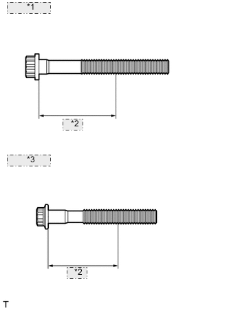
*1 for Bolt A: *2 47 mm *3 for Bolt B: Using a vernier caliper, measure the minimum diameter of the elongated thread at the measuring point.
Measuring point 47 mm (1.85 in.) Standard diameter Item Specified Condition Bolt A 10.8 to 11.0 mm (0.425 to 0.433 in.) Bolt B 9.8 to 10.0 mm (0.386 to 0.394 in.) Minimum diameter Item Specified Condition Bolt A 10.7 mm (0.421 in.) Bolt B 9.7 mm (0.382 in.) If the diameter is less than the minimum, replace the crankshaft bearing cap set bolt.
-