KNOCK SENSOR INSTALLATION
CAUTION / NOTICE / HINT
Tech Tips
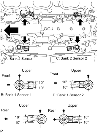
When viewed from the rear of the engine assembly, Bank 1 is on the left side and Bank 2 is on the right side.
PROCEDURE
-
INSTALL KNOCK SENSOR
-
Install the 4 knock sensors with the 4 bolts so that the sensors are angled as shown in the illustration.
- Torque:
- 20 N*m { 204 kgf*cm, 15 ft.*lbf }
Tech Tips
The acceptable installation angle of the knock sensors is between 10° upwards and downwards from the horizontal position.
-
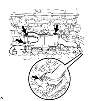
Connect the 4 knock sensor connectors.
-
-
INSTALL SEPARATOR CASE
-
Install the separator case with the 4 bolts.
- Torque:
- 10 N*m { 102 kgf*cm, 7 ft.*lbf }
-
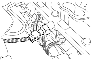
Connect the fuel pressure sensor connector.
-
-
INSTALL NO. 4 FUEL PIPE SUB-ASSEMBLY
-
INSTALL NO. 2 ENGINE COVER SUB-ASSEMBLY LH
-
INSTALL NO. 2 ENGINE COVER SUB-ASSEMBLY
-
INSTALL NO. 1 ENGINE COVER SUB-ASSEMBLY
-
INSTALL INTAKE MANIFOLD