THROTTLE BODY INSTALLATION
PROCEDURE
-
INSTALL THROTTLE BODY ASSEMBLY
-
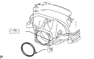
*1 Groove *2 Protrusion Install a new gasket to the intake manifold.
Tech Tips
Align the protrusion of the gasket with the groove on the intake manifold.
-
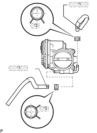
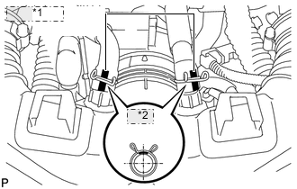
*1 White Paint *2 Lower *3 Front Connect the No. 4 water and No. 5 water by-pass hoses to the throttle body assembly.
Tech Tips
-
Position the claws of the clamps as shown in the illustration.
-
Install the clamps so that they are within the hose's paint marks.
-
-
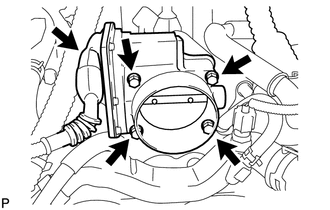
Install the throttle body assembly with the 4 bolts.
- Torque:
- 10 N*m { 102 kgf*cm, 7 ft.*lbf }
-
Connect the throttle body motor connector.
-
-
INSTALL INTAKE AIR CONNECTOR PIPE
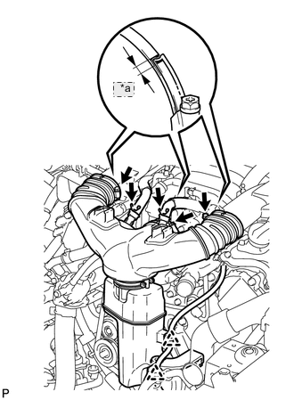
*a 2 mm
-
Align the protrusion of the intake air resonator with the cutout of the bracket and insert the protrusion.
-
Install the intake air connector pipe with the 3 hose clamps.
- Torque:
- for intake air connector pipe and throttle body
- 4.8 N*m { 49 kgf*cm, 42 in.*lbf }
- for intake air connector pipe and intake air resonator
- 3.8 N*m { 39 kgf*cm, 34 in.*lbf }
Note
Insert the protrusion of the intake air connector pipe into the hole of the hose clamp.
Tech Tips
-
The intake air connector pipe and throttle body clamp can be tightened within the range of 4.0 N*m (41 kgf*cm, 35 in.*lbf) to 5.5 N*m (56 kgf*cm, 49 in.*lbf), and the intake air connector pipe and intake air resonator clamp can be tightened within the range of 2.0 N*m (20 kgf*cm, 18 in.*lbf) to 5.5 N*m (56 kgf*cm, 49 in.*lbf).
-
When tightening the hose clamp, make sure the hose clamp's end is within the painted white line (width: 2 mm (0.0787 in.)).
-
Attach the 2 wire harness clamps.
-
*1 White Paint *2 Upper Connect the No. 1 ventilation hose and No. 2 ventilation hose to the intake air connector pipe.
Tech Tips
-
Position the claws of the clamps as shown in the illustration.
-
Install the clamps so that they are within the hose's paint marks.
-
-
-
INSTALL NO. 1 AIR CLEANER INLET
-
ADD ENGINE COOLANT
-
INSPECT FOR COOLANT LEAK
-
INSTALL AIR CLEANER INLET COVER SUB-ASSEMBLY
-
INSTALL V-BANK COVER SUB-ASSEMBLY
-
INSTALL NO. 1 ENGINE UNDER COVER
-
INSTALL FRONT WHEEL OPENING EXTENSION PAD LH
-
INSTALL FRONT WHEEL OPENING EXTENSION PAD RH
-
PERFORM INITIALIZATION
Note
-
Be sure to perform this procedure after reassembling the throttle body assembly or removing and reinstalling any throttle body component.
-
Perform the following procedure after replacing the ECM, throttle body assembly or any throttle body components. The following procedure should also be performed if the throttle body is cleaned.
-
Be sure to perform this procedure after reconnecting the battery cable and replacing the ECM.
-
Disconnect the EFI MAIN, EFI MAIN2 and ETCS fuses at the same time. Wait at least 60 seconds and reconnect the fuses.
-
Turn the ignition switch to the ON position without operating the accelerator pedal.
Note
If the accelerator pedal is operated, perform the above steps again.
-
Connect the Techstream to the DLC3 and clear the DTCs Click here.
-
Put the engine in inspection mode Click here.
-
Start the engine and check that the MIL is not illuminated and that the idle speed is within the specified range when the A/C is switched off after the engine is warmed up.
Standard Tester Display Measurement Item/ Range Normal Condition Diagnostic Note Engine speed Engine speed:
Min.: 0 rpm, Max.: 16383.75 rpm
800 to 900 rpm: Idling Shift lever on P 950 to 1050 rpm: Idling Shift lever on N Note
-
Be sure to perform this step with all accessories off.
-
Make sure that the shift lever is in N or P.
-
-
Enter the following menus: Powertrain / Engine and ETC / Data List / All Data / Throttle Sensor Position. Sensor Output. Fully depress the accelerator pedal and check that the value is 60% or more.
-
Perform a road test and confirm that there are no abnormalities.
-