SFI SYSTEM, Diagnostic DTC:P2237, P2238, P2239, P2240, P2241, P2242, P2252, P2253, P2255, P2256
| DTC Code | DTC Name |
|---|---|
| P2237 | Oxygen (A/F) Sensor Pumping Current Circuit / Open (Bank 1 Sensor 1) |
| P2238 | Oxygen (A/F) Sensor Pumping Current Circuit Low (Bank 1 Sensor 1) |
| P2239 | Oxygen (A/F) Sensor Pumping Current Circuit High (Bank 1 Sensor 1) |
| P2240 | Oxygen (A/F) Sensor Pumping Current Circuit / Open (Bank 2 Sensor 1) |
| P2241 | Oxygen (A/F) Sensor Pumping Current Circuit Low (Bank 2 Sensor 1) |
| P2242 | Oxygen (A/F) Sensor Pumping Current Circuit High (Bank 2 Sensor 1) |
| P2252 | Oxygen (A/F) Sensor Reference Ground Circuit Low (Bank 1 Sensor 1) |
| P2253 | Oxygen (A/F) Sensor Reference Ground Circuit High (Bank 1 Sensor 1) |
| P2255 | Oxygen (A/F) Sensor Reference Ground Circuit Low (Bank 2 Sensor 1) |
| P2256 | Oxygen (A/F) Sensor Reference Ground Circuit High (Bank 2 Sensor 1) |
CAUTION / NOTICE / HINT
DESCRIPTION
Tech Tips
-
Although the DTC titles say oxygen sensor, these DTCs relate to the Air-Fuel Ratio (A/F) sensor.
-
Sensor 1 refers to the sensor mounted in front of the Three-Way Catalytic Converter (TWC) and located near the engine assembly.
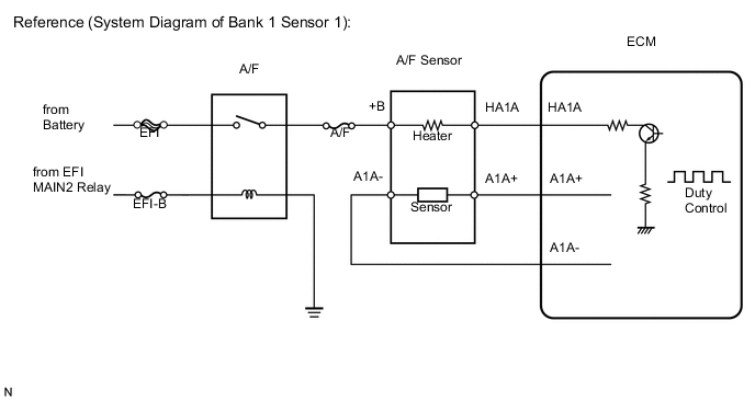
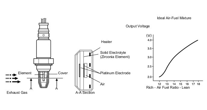
The A/F sensor, which is located between the exhaust manifold and catalyst, consists of alloyed metal elements and a heater.
Depending on the engine operating conditions, the heater heats the sensor elements to activate them. Battery voltage is applied to the heater, the sensor ground is controlled by the ECM using a duty ratio.
The sensor elements convert the oxygen concentration in the exhaust gas into voltage values to output. Based on the voltage, the ECM determines the air-fuel ratio and regulates the fuel injection volume depending on the air-fuel ratio and engine operating conditions. The voltage changes between 0.6 V and 4.5 V while the engine is running. If the air-fuel ratio is lean, which means the oxygen concentration in the exhaust gas is high, the voltage is high. If the air-fuel ratio is rich, which means the oxygen concentration in the exhaust gas is low, the voltage is low.
| DTC No. | DTC Detection Condition | Trouble Area |
|---|---|---|
| P2237 P2240 |
Open in the circuit between terminals AF+ and AF- of the AF sensor while engine is running (2 trip detection logic) |
|
| P2238 P2241 |
Any of the following conditions are met: (2 trip detection logic)
|
|
| P2239 P2242 |
AF+ voltage more than 4.5 V (2 trip detection logic) |
|
| P2252 P2255 |
AF- voltage 0.5 V or less (2 trip detection logic) |
|
| P2253 P2256 |
AF- voltage more than 4.5 V (2 trip detection logic) |
|
MONITOR DESCRIPTION
These DTCs are output when there is an open or short in the A/F sensor circuit, or if A/F sensor output drops. To detect these problems, the voltage of the A/F sensor is monitored when turning the power switch on (IG), and the admittance (admittance is an electrical term that indicates the ease of flow of current) is checked while driving. If the voltage of the A/F sensor is between 0.6 V and 4.5 V, it is considered normal. If the voltage is out of the specified range, or the admittance is less than the standard value, the ECM will determine that there is a malfunction in the A/F sensor. If the same malfunction is detected in next driving cycle, the MIL will be illuminated and a DTC will be stored.
WIRING DIAGRAM
Refer to DTC P2195 Click here.
CAUTION / NOTICE / HINT
Tech Tips
-
Read freeze frame data using the intelligent tester. Freeze frame data records the engine condition when malfunctions are detected. When troubleshooting, freeze frame data can help determine if the vehicle was moving or stationary, if the engine was warmed up or not, if the air-fuel ratio was lean or rich, and other data from the time the malfunction occurred.
-
When viewed from the rear of the engine assembly, Bank 1 is on the left side and Bank 2 is on the right side.
PROCEDURE
-
CHECK HARNESS AND CONNECTOR (A/F SENSOR - ECM)
-
Turn the power switch off.
-
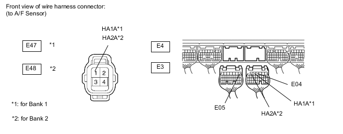
Disconnect the E3 and E4 ECM connectors.
-
Measure the resistance according to the value(s) in the table below.
Standard resistance (Check for open) Tester Connection Condition Specified Condition E47-1 (HA1A) - E3-5 (HA1A) Always Below 1 Ω E48-1 (HA2A) - E3-6 (HA2A) Always Below 1 Ω E3-4 (E04) - Body ground Always Below 1 Ω E4-1 (E05) - Body ground Always Below 1 Ω Standard resistance (Check for short) Tester Connection Condition Specified Condition E47-1 (HA1A) or E3-5 (HA1A) - Body ground Always 10 kΩ or higher E48-1 (HA2A) or E3-6 (HA2A) - Body ground Always 10 kΩ or higher
NG 
REPAIR OR REPLACE HARNESS OR CONNECTOR
OK 
-
-
REPLACE AIR FUEL RATIO SENSOR
-
Replace the air-fuel ratio sensor Click here.
NEXT
-
-
CHECK WHETHER DTC OUTPUT RECURS
-
Put the engine in inspection mode Click here.
-
Connect the intelligent tester to the DLC3.
-
Turn the tester ON.
-
Clear the DTCs Click here.
-
Allow the engine to idle for 5 minutes or more.
-
Enter the following menus: Powertrain / Engine and ECT / DTC / Pending.
-
Read pending DTCs.
Result Display (DTC Output) Proceed to No output A P2237, P2240, P2238, P2241, P2239, P2242, P2252, P2255, P2253 or P2256 B
A
END
B
REPLACE ECM Click here
-