SFI SYSTEM, Diagnostic DTC:P0190, P0192, P0193
| DTC Code | DTC Name |
|---|---|
| P0190 | Fuel Rail Pressure Sensor Circuit |
| P0192 | Fuel Rail Pressure Sensor Circuit Low Input |
| P0193 | Fuel Rail Pressure Sensor Circuit High Input |
DESCRIPTION
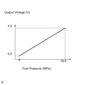
The fuel pressure sensors located on the delivery pipe (fuel rail) detect the fuel pressure as voltages. The engine control module (ECM) applies a 5-volt reference voltage to the sensor. The sensor varies the voltage between 0.5 V and 4.5 V in accordance with the fuel pressure. The ECM calculates the fuel pressure by the sensor voltage, and regulates the fuel pressure for the direct fuel injection system.
| DTC No. | DTC Detection Condition | Trouble Area |
|---|---|---|
| P0190 | Open or short in fuel pressure sensor circuit for 5 seconds or more (1 trip detection logic) |
|
| P0192 | Short in fuel pressure sensor circuit for 5 seconds or more (1 trip detection logic) |
|
| P0193 | Open in fuel pressure sensor circuit for 5 seconds or more (1 trip detection logic) |
|
Tech Tips
After confirming DTC P0190, use the intelligent tester to confirm the fuel pressure in the delivery pipe by entering the following menus: Powertrain / Engine and ECT / Data List / All Data / Fuel Press.
| Fuel Pressure (kPa) | Malfunction |
|---|---|
| Approximately 0 | PR, E2 circuit short |
| 19600 or more |
|
MONITOR DESCRIPTION
These DTCs are set if the fuel pressure sensor output voltage is out of the standard range. The DTCs stand for an open or short malfunction of the sensor circuit.
If these DTCs are set, the ECM enters fail-safe mode and limits the engine power. Fail-safe mode continues until the power switch is turned off.
WIRING DIAGRAM
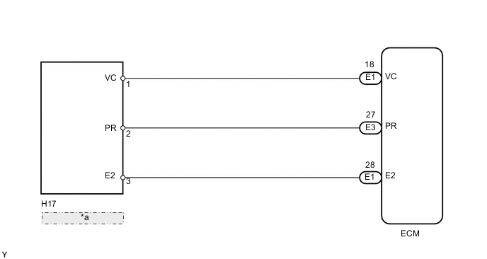
| *a | Fuel Pressure Sensor |
CAUTION / NOTICE / HINT
Tech Tips
Read freeze frame data using the intelligent tester. Freeze frame data records the engine condition when malfunctions are detected. When troubleshooting, freeze frame data can help determine if the vehicle was moving or stationary, if the engine was warmed up or not, if the air-fuel ratio was lean or rich, and other data from the time the malfunction occurred.
PROCEDURE
-
READ VALUE USING INTELLIGENT TESTER (FUEL PRESSURE)
-
Connect the intelligent tester to the DLC3.
-
Turn the power switch on (IG).
-
Turn the tester ON.
-
Put the engine in inspection mode Click here.
-
Enter the following menus: Powertrain / Engine and ECT / Data List / All Data / Fuel Press.
-
Read the values.
Pressure 4000 to 13000 kPa (40.8 to 132.6 kgf/cm2, 580 to 1885 psi). Result: Fuel Press (kPa) Proceed to 19600 or more A 0.0 A OK (4000 to 13000 kPa (40.8 to 132.6 kgf/cm2, 580 to 1885 psi)) *
B Tech Tips
*: The value must change when the engine is running or stopped.
B 
CHECK FOR INTERMITTENT PROBLEMS Click here
A 
-
-
CHECK HARNESS AND CONNECTOR (FUEL PRESSURE SENSOR - ECM)
-
Disconnect the H17 fuel pressure sensor connector.
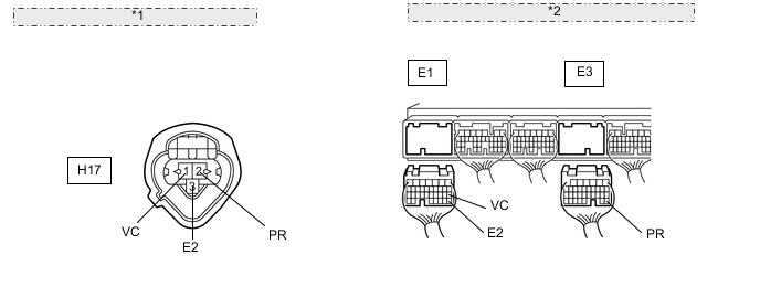
*1 Front view of wire harness connector: (to Fuel Pressure Sensor) *2 Rear view of wire harness connector: (to ECM) -
Disconnect the E1 and E3 ECM connectors.
-
Measure the resistance according to the value(s) in the table below.
Standard resistance (Check for open) Tester Connection Condition Specified Condition H17-1 (VC) - E1-18 (VC) Always Below 1 Ω H17-2 (PR) - E3-27 (PR) Always Below 1 Ω H17-3 (E2) - E1-28 (E2) Always Below 1 Ω Standard resistance (Check for short) Tester Connection Condition Specified Condition H17-1 (VC) or E1-18 (VC) - Body ground Always 10 kΩ or higher H17-2 (PR) or E3-27 (PR) - Body ground Always 10 kΩ or higher
NG
REPAIR OR REPLACE HARNESS OR CONNECTOR
OK
-
-
INSPECT ECM (VC VOLTAGE)
-
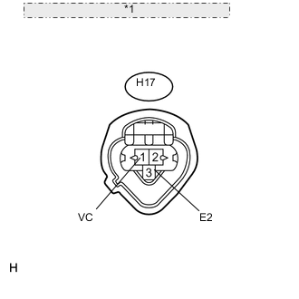
*1 Front view of wire harness connector: (to Fuel Pressure Sensor) Disconnect the H17 fuel pressure sensor connector.
-
Measure the voltage according to the value(s) in the table below.
Standard voltage Tester Connection Switch Condition Specified Condition H17-1 (VC) - H17-3 (E2) Power switch on (IG) 4.5 to 5.5 V
NG
REPLACE ECM Click here
OK
-
-
REPLACE FUEL DELIVERY PIPE SUB-ASSEMBLY LH (FUEL PRESSURE SENSOR)
-
Replace the fuel delivery pipe sub-assembly LH (fuel pressure sensor) Click here.
NEXT
-
-
CHECK IF DTC RECURS
-
Connect the intelligent tester to the DLC3.
-
Turn the power switch on (IG).
-
Turn the tester ON.
-
Put the engine in inspection mode Click here.
-
Enter the following menus: Powertrain / Engine and ECT / DTC.
-
Read the DTCs.
Result Display (DTC Output) Proceed to P0190, P0192 and/or P0193 A No output B
A
REPLACE ECM Click here
B
END
-