SFI SYSTEM, Diagnostic DTC:P0171, P0172, P0174, P0175, P1170, P117B
| DTC Code | DTC Name |
|---|---|
| P0171 | System Too Lean (Bank 1) |
| P0172 | System Too Rich (Bank 1) |
| P0174 | System Too Lean (Bank 2) |
| P0175 | System Too Rich (Bank 2) |
| P1170 | Port Injector Fuel Performance |
| P117B | Direct Injector Fuel Performance |
DESCRIPTION
The fuel trim is related to the feedback compensation value, not to the basic injection time. The fuel trim consists of both the short-term and the long-term fuel trim.
The short-term fuel trim is fuel compensation that is used to constantly maintain the air-fuel ratio at stoichiometric levels. The signal from the Air-Fuel Ratio (A/F) sensor indicates whether the air-fuel ratio is rich or lean compared to the stoichiometric ratio. This triggers a reduction in the fuel injection volume if the air-fuel ratio is rich and an increase in the fuel injection volume if it is lean.
Factors such as individual engine differences, wear over time and changes in operating environment cause short-term fuel trim to vary from the ideal theoretical value. The long-term fuel trim controls overall fuel compensation. The long-term fuel trim compensates for long term deviations of the fuel trim from the ideal theoretical value. These long term deviations result from the corrections made by the short-term fuel trim.
If both the short-term fuel and long-term fuel trims are lean or rich beyond predetermined values, it is interpreted as a malfunction, and the ECM illuminates the MIL and sets a DTC.
| DTC No. | DTC Detection Condition | Trouble Area |
|---|---|---|
| P0171 P0174 |
Fuel trim is too lean (2 trip detection logic) |
|
| P0172 P0175 |
Fuel trim is too rich (2 trip detection logic) |
|
| P1170 | With stable air fuel ratio feedback, a fuel injection system malfunction has been detected and fuel trim of the port injection is unusually rich or lean side. |
|
| P117B | With stable air fuel ratio feedback, a fuel injection system malfunction has been detected and fuel trim of the direct injection is unusually rich or lean side. |
Tech Tips
-
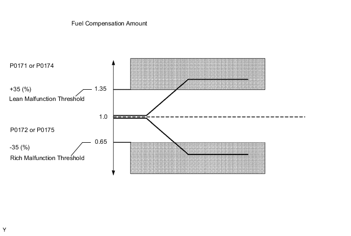
When DTC P0171 or P0174 is set, the actual air-fuel ratio is on the lean side. When DTC P0172 or P0175 is set, the actual air-fuel ratio is on the rich side.
-
If the vehicle runs out of fuel, the air-fuel ratio is lean and DTC P0171 or P0174 may be set. The MIL is then illuminated.
-
When DTC P1170 or P117B is output , it may not be possible to precisely determine whether the port injection or the direct injection is malfunctioning, depending on the conditions. In this case, perform an Active Test (control the injection way) to determine which injection system is malfunctioning.
MONITOR DESCRIPTION
Under closed-loop fuel control, fuel injection volumes that deviate from those estimated by the ECM cause changes in the long-term fuel trim compensation value. The long-term fuel trim is adjusted when there are persistent deviations in the short-term fuel trim values. Deviations from the ECM's estimated fuel injection volumes also affect the average fuel trim learning value, which is a combination of the average short-term fuel trim (fuel feedback compensation value) and the average long-term fuel trim (learning value of the air-fuel ratio). If the average fuel trim learning value exceeds the malfunction threshold, the ECM interprets this as a fault in the fuel system and sets a DTC.
-
Example:
-
If the average fuel trim learning value is 35% or more or -35% or less, the ECM interprets this as a fuel system malfunction.
WIRING DIAGRAM
Refer to DTC P2195 Click here.
CAUTION / NOTICE / HINT
Tech Tips
-
Read freeze frame data using the GTS. Freeze frame data records the engine condition when malfunctions are detected. When troubleshooting, freeze frame data can help determine if the vehicle was moving or stationary, if the engine was warmed up or not, if the air-fuel ratio was lean or rich, and other data from the time the malfunction occurred.
-
When viewed from the rear of the engine assembly, Bank 1 is on the left side and Bank 2 is on the right side.
-
A low A/F sensor voltage could be caused by a rich air-fuel mixture. Check for conditions that would cause the engine to run rich.
-
A high A/F sensor voltage could be caused by a lean air-fuel mixture. Check for conditions that would cause the engine to run lean.
PROCEDURE
-
CHECK ANY OTHER DTCS OUTPUT (IN ADDITION TO DTC P0171, P0172, P0174, P0175, P1170 OR P117B)
-
Connect the GTS to the DLC3.
-
Turn the power switch on (IG) and turn the tester ON.
-
Enter the following menus: Powertrain / Engine and ECT / DTC.
-
Read the DTCs.
Result Display (DTC output) Proceed to P0171, P0172, P0174 or P0175, P1170 and/or P117B are output A P0171, P0172, P0174 or P0175, P1170 and/or P117B and other DTCs B Tech Tips
If any DTCs other than P0171, P0172, P0174 or P0175, P1170 or P117B are output, troubleshoot those DTCs first.
B 
GO TO DTC CHART Click here
A 
-
-
READ VALUE USING GTS
-
Put the engine in inspection mode Click here.
-
Connect the GTS to the DLC3.
-
Turn the tester ON.
-
Enter the following menus: Powertrain / Engine and ECT / Active Test / Control the Injection Way / Port.
-
Read the values of the following menus: Data List / A/F Control System / Short FT #1 and Long FT #1 and/or Short FT #2 and Long FT #2.
OK Short FT #1, #2 + Long FT #1, #2 = Between -19% and +19% -
Enter the following menus: Powertrain / Engine and ECT / Active Test / Control the Injection Way / Direct.
-
Read the value of the following menus: Data List / A/F Control System / Short FT #1 and Long FT #1 and/or Short FT #2 and Long FT #2.
OK Short FT #1, #2 + Long FT #1, #2 = Between -19% and +19% Result Item Proceed to Port Direct OK OK A OK NG B NG OK C NG NG D
B 
CHECK FUEL DELIVERY PIPE SUB-ASSEMBLY LH (FUEL PRESSURE SENSOR) Click here
C
CHECK FUEL INJECTOR (for Port Injection) Click here
D
CHECK PCV HOSE Click here
A
-
-
CHECK FOR INTERMITTENT PROBLEMS
Tech Tips
-
By repeating short trips*, when warming up the engine, gasoline evaporates and blow-by gas increases. As a result, DTC P0172 and/or DTC P0175 may be output.
-
*: Driving time (distance) from turning the power switch on (READY) until turning it off is short.
NEXT
END
-
-
CHECK PCV HOSE
OK PCV hose is connected correctly and is not damaged.
NG
REPAIR OR REPLACE PCV HOSE Click here
OK
-
CHECK AIR INDUCTION SYSTEM
-
Check the air induction system for vacuum leakage Click here.
OK No leakage from air induction system.
NG
REPAIR OR REPLACE AIR INDUCTION SYSTEM
OK
-
-
PERFORM ACTIVE TEST USING GTS
-
Put the engine in inspection mode Click here.
-
Connect the GTS to the DLC3.
-
Turn the tester ON.
-
Warm up the engine at an engine speed of 2500 rpm for approximately 90 seconds.
-
Enter the following menus: Powertrain / Engine and ECT / Active Test / Control the Injection Volume for A/F Sensor.
-
Perform the Active Test operation with the engine in an idling condition (press the RIGHT or LEFT button to change the fuel injection volume).
-
Monitor the output voltages of the A/F and HO2 sensors (AFS Voltage B1S1 and O2S B1S2 or AFS Voltage B2S1 and O2S B2S2) displayed on the tester.
Tech Tips
-
Change the fuel injection volume within the range of -12.5% to +12.5%.
-
Each sensor reacts in accordance with increases and decreases in the fuel injection volume.
-
The air fuel ratio sensor has an output delay of a few seconds and the heated oxygen sensor has a maximum output delay of approximately 20 seconds.
Tester Display (Sensor) Injection Volume Status Voltage AFS Voltage B1S1 or AFS Voltage B2S1
(A/F)
+12.5% Rich Less than 3.0 V AFS Voltage B1S1 or AFS Voltage B2S1
(A/F)
-12.5% Lean More than 3.35 V O2S B1S2 or O2S B2S2
(HO2)
+12.5% Rich More than 0.55 V O2S B1S2 or O2S B2S2
(HO2)
-12.5% Lean Less than 0.4 V Result Status
AFS Voltage B1S1
or
AFS Voltage B2S1
Status
O2S B1S2
or
O2S B2S2
A/F Condition and
A/F Sensor Condition
Suspected Trouble Area Proceed to Lean/Rich Lean/Rich Normal - A Lean Lean Actual air-fuel ratio lean
-
PCV valve and hose
-
PCV hose connections
-
Fuel injector (for port injection)
-
Fuel injector (for direct injection)
-
Gas leakage from exhaust system
-
Air induction system
-
Fuel pressure
-
Mass Air Flow (MAF) meter
-
Engine Coolant Temperature (ECT) sensor
A Rich Rich Actual air-fuel ratio rich
-
Fuel injector (for port injection)
-
Fuel injector (for direct injection)
-
Gas leakage from exhaust system
-
Ignition system
-
Fuel pressure
-
MAF meter
-
ECT sensor
A Lean Lean/Rich A/F sensor malfunction
-
A/F sensor
B Rich Lean/Rich A/F sensor malfunction
-
A/F sensor
B
-
Lean:
-
During Control the Injection Volume for A/F sensor, the A/F sensor output voltage (AFS) is consistently more than 3.35 V, and the HO2 sensor output voltage (O2S) is consistently less than 0.4 V.
-
Rich:
-
During Control the Injection Volume for A/F sensor, the AFS is consistently less than 3.0 V, and the O2S is consistently more than 0.55 V.
-
B
INSPECT AIR FUEL RATIO SENSOR (HEATER RESISTANCE) Click here
A
-
-
READ VALUE USING GTS (COOLANT TEMP)
-
Connect the GTS to the DLC3.
-
Turn the power switch on (IG) and turn the tester ON.
-
Enter the following menus: Powertrain / Engine and ECT / Data List / All Data / Coolant Temp.
-
Read the Data List twice when the engine is both cold and warmed up.
Standard With cold engine Same as ambient air temperature. With warm engine Between 75 and 95°C (167 and 203°F)
NG
REPLACE ENGINE COOLANT TEMPERATURE SENSOR Click here
OK
-
-
INSPECT MASS AIR FLOW METER (for Bank 1 or Bank 2)
-
Inspect the mass air flow meter Click here.
NG
REPLACE MASS AIR FLOW METER (for Bank 1 or Bank 2) Click here
OK
-
-
CHECK FOR EXHAUST GAS LEAK
-
Check for exhaust gas leak Click here.
OK No gas leakage.
NG
REPAIR OR REPLACE EXHAUST SYSTEM
OK
-
-
INSPECT AIR FUEL RATIO SENSOR (HEATER RESISTANCE)
-
Turn the power switch off.
-
Disconnect the A/F sensor connector.
-
Measure the resistance according to the value(s) in the table below.
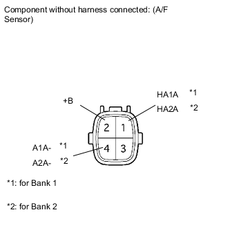
Standard resistance Bank 1 Sensor 1 Tester Connection Condition Specified Condition 1 (HA1A) - 2 (+B) 20°C (68°F) 1.8 to 3.4 Ω 1 (HA1A) - 4 (A1A-) Always 10 kΩ or higher Bank 2 Sensor 1 Tester Connection Condition Specified Condition 1 (HA2A) - 2 (+B) 20°C (68°F) 1.8 to 3.4 Ω 1 (HA2A) - 4 (A2A-) Always 10 kΩ or higher
NG
REPLACE AIR FUEL RATIO SENSOR Click here
OK
-
-
CHECK HARNESS AND CONNECTOR (A/F SENSOR - ECM)
-
Turn the power switch off.
-
Disconnect the E3 and E4 ECM connectors.
-
Measure the resistance according to the value(s) in the table below.
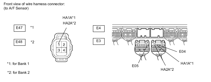
Standard resistance (Check for open) Tester Connection Condition Specified Condition E47-1 (HA1A) - E3-5 (HA1A) Always Below 1 Ω E48-1 (HA2A) - E3-6 (HA2A) Always Below 1 Ω E3-4 (E04) - Body ground Always Below 1 Ω E4-1 (E05) - Body ground Always Below 1 Ω Standard resistance (Check for short) Tester Connection Condition Specified Condition E47-1 (HA1A) or E3-5 (HA1A) - Body ground Always 10 kΩ or higher E48-1 (HA2A) or E3-6 (HA2A) - Body ground Always 10 kΩ or higher
NG
REPAIR OR REPLACE HARNESS OR CONNECTOR
OK
-
-
REPLACE AIR FUEL RATIO SENSOR
-
Replace the air fuel ratio sensor Click here.
NEXT
-
-
PERFORM CONFIRMATION DRIVING PATTERN
-
Connect the GTS to the DLC3.
-
Turn the power switch on (IG).
-
Turn the tester ON.
-
Clear DTCs Click here.
-
Put the engine in inspection mode (maintenance mode) Click here.
-
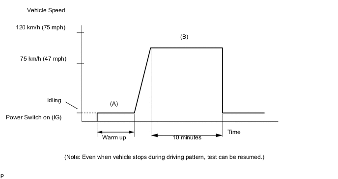
Warm up the engine with all the accessories switched OFF. (Procedure "A")
-
Drive the vehicle at between 75 km/h and 120 km/h (47 mph and 75 mph) and at an engine speed of between 1400 rpm and 3200 rpm for 10 minutes. (Procedure "B")
Tech Tips
If the system is still malfunctioning, the MIL will be illuminated during procedure "B".
Note
If the conditions in this test are not strictly followed, no malfunction will be detected.
NEXT
-
-
CHECK WHETHER DTC OUTPUT RECURS (DTC P0171, P0172, P0174, P0175, P1170 OR P117B)
-
Enter the following menus: Powertrain / Engine and ECT / DTC.
-
Read the DTCs.
Result Display (DTC output) Proceed to P0171, P0172, P0174, P0175, P1170 and/or P117B are output A No output B
B
END
A
-
-
CHECK FUEL PRESSURE (LOW PRESSURE)
-
Check the fuel pressure Click here.
OK
REPLACE ECM Click here
NG
-
-
CHECK FUEL PUMP OPERATION
-
Check the fuel pump operation Click here.
NG
REPLACE FUEL PUMP Click here
OK
-
-
CHECK FUEL LEAK (LOW PRESSURE SIDE)
-
Check fuel leak Click here.
OK No leakage
OK
CHECK AND REPLACE FUEL PUMP, PRESSURE REGULATOR, FUEL PIPE LINE AND FILTER
NG
REPAIR OR REPLACE FUEL SYSTEM
-
-
CHECK FUEL DELIVERY PIPE SUB-ASSEMBLY LH (FUEL PRESSURE SENSOR)
-
Put the engine in inspection mode Click here.
-
Connect the GTS to the DLC3.
-
Turn the tester ON.
-
Enter the following menus: Powertrain / Engine and ECT / Data List / All Data / Fuel Press.
-
While revving the engine, check that the fuel pressure fluctuates.
Standard Idling 3500 to 4500 kPa 2500 rpm (Depress accelerator pedal fully) 7000 to 9000 kPa Tech Tips
The A/C switch and all accessory switches should be OFF, the shift lever should be in the N or P position, and the engine should be fully warmed up.
NG
REPAIR OR REPLACE FUEL SYSTEM FOR HIGH PRESSURE SIDE Click here
OK
-
-
READ VALUE USING GTS
-
Put the engine in inspection mode Click here.
-
Connect the GTS to the DLC3.
-
Turn the tester ON.
-
Enter the following menus: Powertrain / Engine and ECT / Active Test / Control the Injection way / Direct.
Tech Tips
The A/C switch and all accessory switches should be OFF, the shift lever should be in the N or P position, and the engine should be fully warmed up.
-
Read the value of the following menus: Data List / A/F Control System / Short FT #1, Long FT #1, Short FT #2, Long FT #2 and Fuel Pump Duty (D4).
Result Item Proceed to Fuel Pump Duty (D4) Short FT #1 + Long FT #1 Short FT #2 + Long FT #2 40% or more -20% or less -20% or less A 10% or less +20% or more +20% or more A 40% or more +20% or more +20% or more B 10% or less -20% or less -20% or less C 10% to 40% - - D
A
REPLACE FUEL DELIVERY PIPE SUB-ASSEMBLY LH (FUEL PRESSURE SENSOR) Click here
B
INSPECT FUEL RELIEF VALVE Click here
C
REPLACE ECM Click here
D
-
-
READ VALUE USING GTS
-
Put the engine in inspection mode Click here.
-
Connect the GTS to the DLC3.
-
Turn the tester ON.
-
Enter the following menus: Powertrain / Engine and ECT / Active Test / Control the Injection way / Direct.
Tech Tips
The A/C switch and all accessory switches should be OFF, the shift lever should be in the N or P position, and the engine should be fully warmed up.
-
Read the value of Data List of the following menus: Data List / A/F Control System / Short FT #1, Long FT #1, Short FT #2, Long FT #2 and Fuel Pump Duty (D4).
Result Item Proceed to Fuel Pump Duty (D4) Short FT #1 + Long FT #1 Short FT #2 + Long FT #2 10% to 40% -25% or less -25% or less A 10% to 40% -25% or less -25% to +25% B 10% to 40% -25% to +25% -25% or less C 10% to 40% +30% or more +30% or more A 10% to 40% +25% or more -25% to +25% B 10% to 40% -25% to +25% +25% or more C 10% to 40% -25% to +25% -25% to +25% D
A
REPLACE FUEL INJECTOR (for Direct Injection) (ALL CYLINDERS) Click here
B
REPLACE FUEL INJECTOR (for Direct Injection) (BANK 1 SIDE) Click here
C
REPLACE FUEL INJECTOR (for Direct Injection) (BANK 2 SIDE) Click here
D
CHECK FOR INTERMITTENT PROBLEMS Click here
-
-
INSPECT FUEL RELIEF VALVE
-
Put the engine in inspection mode Click here.
-
Warm up the engine.
-
Connect the GTS to the DLC3.
-
Turn the tester ON.
-
Enter the following menus: Powertrain / Engine and ECT / Data List / Primary / Fuel Press and Coolant Temp and Battery Voltage.
Note
Check that the following conditions are met.
-
Coolant Temp value is 50°C (122°F) or more
-
Battery Voltage value is 10 V or more
-
Fuel Press value is 2000 kPa or more
-
-
Turn the power switch off.
Tech Tips
Before turning the power switch off, write down the Fuel Press value.
-
Wait for 10 seconds.
-
Put the engine in inspection mode Click here.
-
After starting the engine, turn the power switch off within 45 seconds.
-
Wait for 10 seconds. Then turn the power switch on (IG).
-
Enter the following menus: Powertrain / Engine and ECT / Data List / Primary / Fuel Press.
-
Check the fuel pressure.
OK Fuel pressure is stable.
OK
CHECK AND REPLACE FUEL PUMP (for High Pressure) Click here
NG
REPLACE FUEL RELIEF VALVE Click here
-
-
CHECK FUEL INJECTOR (for Port Injection)
-
Check the injection volume (whether fuel volume is high or low, and whether injection pattern is poor) Click here.
OK
REPLACE ECM Click here
NG
REPLACE FUEL INJECTOR (for Port Injection) Click here
-