SFI SYSTEM, Diagnostic DTC:P0012, P0022
| DTC Code | DTC Name |
|---|---|
| P0012 | Camshaft Position "A" - Timing Over-Retarded (Bank 1) |
| P0022 | Camshaft Position "A" - Timing Over-Retarded (Bank 2) |
DESCRIPTION
Refer to DTC P0010 Click here.
| DTC No. | DTC Detection Condition | Trouble Area |
|---|---|---|
| P0012 | With engine warmed up and while driving in urban area (engine speed 4000 rpm or less), valve timing on bank 1 intake side remains in retarded position for 5 minutes or more (2 trip detection logic) |
|
| P0022 | With engine warmed up and while driving in urban area (engine speed 4000 rpm or less), valve timing on bank 2 intake side remains in retarded position for 5 minutes or more (2 trip detection logic) |
|
| Vehicle Condition | Fail-Safe |
|---|---|
|
|
MONITOR DESCRIPTION
This DTC is output when a valve timing fixed condition is detected. With the engine speed at 4000 rpm or less in the retard angle position, if the valve timing does not vary, and there is a large difference in the target and actual valve timing, it is determined that a malfunction has occurred. If this condition is detected while driving, a DTC is output (2 trip detection logic).
After the engine is warmed up, a DTC is output if the following occurs: 1) the vehicle is driven in an urban area for 5 minutes, and then the power switch is turned off; and 2) the engine is started and the vehicle is driven in an urban area for 5 minutes.
CAUTION / NOTICE / HINT
Tech Tips
-
By using the Active Test's Control the VVT-iE Linear (Bank1) or Control the VVT-iE Linear (Bank2) function, it can be determined if the VVT-iE system is malfunctioning.
-
Put the engine in inspection mode Click here.
-
Connect the intelligent tester to the DLC3.
-
Turn the tester ON.
-
Clear the DTC Click here.
-
Warm up the engine.
-
Enter the following menus: Powertrain / Engine and ECT / Active Test / Control the VVT-iE Linear (Bank1) or Control the VVT-iE Linear (Bank2) / All Data / VVT-iE Aim Angle #1 and VVT Change Angle #1 or VVT-iE Aim Angle #2 and VVT Change Angle #2.
-
Perform the Active Test operation with the engine speed at 1500 rpm.
OK Active Test Movement Order Difference between "VVT-iE Aim Angle" and "VVT Change Angle" 0 deg → 10 deg → 20 deg → 40 deg → 10 deg → 0 deg → 10 deg → END Within 4 DegFR -
Read freeze frame data using the intelligent tester. Freeze frame data records the engine condition when malfunctions are detected. When troubleshooting, freeze frame data can help determine if the vehicle was moving or stationary, if the engine was warmed up or not, if the air-fuel ratio was lean or rich, and other data from the time the malfunction occurred.
-
When viewed from the rear of the engine assembly, Bank 1 is on the left side and Bank 2 is on the right side.
PROCEDURE
-
CHECK ANY OTHER DTCS OUTPUT (IN ADDITION TO DTC P0012 OR P0022)
-
Connect the intelligent tester to the DLC3.
-
Turn the power switch on (IG).
-
Turn the tester ON.
-
Enter the following menus: Powertrain / Engine and ECT / DTC.
-
Read DTCs.
Result Display (DTC Output) Proceed to P0012 or P0022 A P0012 or P0022 and other DTCs B
NG 
GO TO DTC CHART Click here
OK 
-
-
INSPECT CAMSHAFT TIMING GEAR ASSEMBLY (for Bank 1 or Bank 2)
-
Turn the power switch off.
-
Remove the camshaft timing control motor assembly (for Bank 1 or Bank 2) Click here.
-
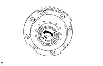
Check if the camshaft timing gear assembly's eccentric shaft rotates smoothly.
OK Rotates smoothly
NG
REPLACE CAMSHAFT TIMING GEAR ASSEMBLY (for Bank 1 or Bank 2) Click here
OK
-
-
REPLACE CAMSHAFT TIMING CONTROL MOTOR ASSEMBLY (for Bank 1 or Bank 2)
-
Replace camshaft timing control motor assembly (for Bank 1 or Bank 2) Click here.
NEXT
-
-
CONFIRM WHETHER MALFUNCTION HAS BEEN SUCCESSFULLY REPAIRED
-
Connect the intelligent tester to the DLC3.
-
Turn the power switch on (IG).
-
Turn the tester ON.
-
Clear DTCs Click here.
-
Turn the power switch off and wait for at least 30 seconds.
-
Turn the power switch on (IG) and turn the intelligent tester on.
-
Put the engine in inspection mode (maintenance mode) Click here.
-
Drive the vehicle in an urban area for approximately 5 minutes.
-
Enter the following menus: Powertrain / Engine and ECT / DTC.
-
Read the DTCs.
Result Display (DTC Output) Proceed to No output A Other DTCs B
A
END
B
GO TO DTC CHART Click here
-