SFI SYSTEM, Diagnostic DTC:P0010, P0020
| DTC Code | DTC Name |
|---|---|
| P0010 | Camshaft Position "A" Actuator Circuit (Bank 1) |
| P0020 | Camshaft Position "A" Actuator Circuit (Bank 2) |
DESCRIPTION
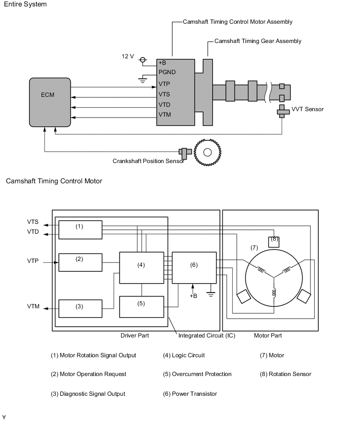
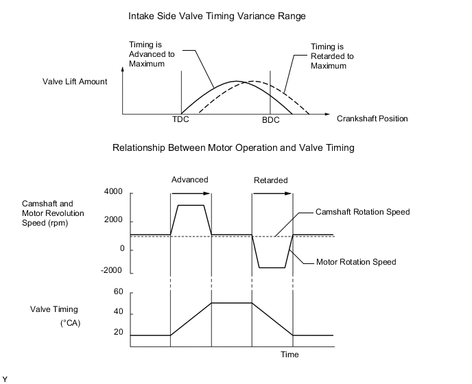
The VVT-iE system changes the valve timing with the motor.
The camshaft control timing motor is equipped with a self diagnostic function, which is used to output diagnosis signals (VTM) to the ECM.
| Part and Terminal Name | Function |
|---|---|
| Camshaft timing control motor | Through its electric motor, operates camshaft timing gear assembly. Interior driver (EDU) detects motor rpm and rotation direction, and performs malfunction diagnosis of motor control. |
| Camshaft timing gear assembly | Changes valve timing by rotating timing chain sprocket |
| ECM | Outputs target rpm and motor rotation direction in response to driving conditions |
| +B | Power supply (when power switch on (IG), 12 V or more) |
| PGND | Power supply ground |
| VTP | Inputs motor activation signal from ECM |
| VTS | Outputs actual motor rpm |
| VTD | Outputs actual rotation direction |
| VTM | Outputs malfunction diagnosis results as a duty ratio in response to following conditions:
|
| Vehicle Condition | Fail-Safe |
|---|---|
|
|
| DTC No. | DTC Detection Condition | Trouble Area |
|---|---|---|
| P0010 | One of following is detected in camshaft timing control motor for 3 seconds: 1) IC has overheated; 2) motor is open; or 3) motor has overcurrent (1 trip detection logic) |
|
| P0020 | One of following is detected in camshaft timing control motor for 3 seconds: 1) IC has overheated; 2) motor is open; or 3) motor has overcurrent (1 trip detection logic) |
|
MONITOR DESCRIPTION
This DTC is output when an IC overheat malfunction or an overcurrent malfunction is detected in the intake side camshaft timing control motor. The camshaft timing control motor is equipped with a self diagnostic function, which is used to output diagnosis signals (VTM) to the ECM. If the ECM receives a motor driver interior malfunction signal, a DTC is output immediately (1 trip detection logic). If the engine is idled for 10 seconds, a DTC is detected.
CAUTION / NOTICE / HINT
Tech Tips
-
Read freeze frame data using the intelligent tester. Freeze frame data records the engine condition when malfunctions are detected. When troubleshooting, freeze frame data can help determine if the vehicle was moving or stationary, if the engine was warmed up or not, if the air-fuel ratio was lean or rich, and other data from the time the malfunction occurred.
-
When viewed from the rear of the engine assembly, Bank 1 is on the left side and Bank 2 is on the right side.
PROCEDURE
-
INSPECT CAMSHAFT TIMING GEAR ASSEMBLY (for Bank 1 or Bank 2)
-
Turn the power switch off.
-
Remove the camshaft timing control motor assembly (for Bank 1 or Bank 2) Click here.
-
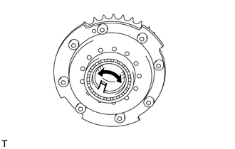
Check if the camshaft timing gear assembly's eccentric shaft rotates smoothly.
OK Rotates smoothly
OK 
REPLACE CAMSHAFT TIMING CONTROL MOTOR ASSEMBLY (for Bank 1 or Bank 2) Click here
NG
REPLACE CAMSHAFT TIMING GEAR ASSEMBLY (for Bank 1 or Bank 2) Click here
-