SFI SYSTEM, Diagnostic DTC:P0201, P0202, P0203, P0204, P0205, P0206, P0207, P0208, P062D, P062E
| DTC Code | DTC Name |
|---|---|
| P0201 | Injector Circuit / Open - (Cylinder 1) |
| P0202 | Injector Circuit / Open - (Cylinder 2) |
| P0203 | Injector Circuit / Open - (Cylinder 3) |
| P0204 | Injector Circuit / Open - (Cylinder 4) |
| P0205 | Injector Circuit / Open - (Cylinder 5) |
| P0206 | Injector Circuit / Open - (Cylinder 6) |
| P0207 | Injector Circuit / Open - (Cylinder 7) |
| P0208 | Injector Circuit / Open - (Cylinder 8) |
| P062D | Fuel Injector Driver Circuit Performance Bank1 |
| P062E | Fuel Injector Driver Circuit Performance Bank2 |
DESCRIPTION
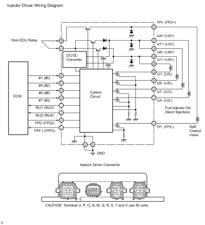
The D-4S (Direct injection 4-stroke gasoline engine superior) has two fuel injection systems. One is the port fuel injection. The other is the direct fuel injection.
In the direct fuel injection system, the injector driver operates the fuel injector (for Direct Injection) using DC 50 V. This voltage is built up by the internal DC-DC converter of the injector driver. The engine control module (ECM) controls the injector driver according to the engine conditions.
The two injector drivers are used to control this engine. The No. 1 injector driver operates the direct fuel injectors #1, #4, #6, #7. The No. 2 injector driver operates the direct fuel injectors #2, #3, #5, #8.
| INJ No. | Injector Driver Group | Fuel Injector Group |
|---|---|---|
| INJ1 | No. 1 Injector Driver |
|
| INJ2 |
|
|
| INJ3 | No. 2 Injector Driver |
|
| INJ4 |
|
| DTC No. | DTC Detection Condition | Trouble Area |
|---|---|---|
| P0201 | Either of following is detected (1 trip detection logic):
|
|
| P0202 | Either of following is detected (1 trip detection logic):
|
|
| P0203 | Either of following is detected (1 trip detection logic):
|
|
| P0204 | Either of following is detected (1 trip detection logic):
|
|
| P0205 | Either of following is detected (1 trip detection logic):
|
|
| P0206 | Either of following is detected (1 trip detection logic):
|
|
| P0207 | Either of following is detected (1 trip detection logic):
|
|
| P0208 | Either of following is detected (1 trip detection logic):
|
|
| P062D | INJ1 and INJ2 signals are not input for 10 consecutive revolutions (1 trip detection logic) | |
| P062E | INJ3 and INJ4 signals are not input for 10 consecutive revolutions (1 trip detection logic) |
MONITOR DESCRIPTION
The injector driver sends the injection confirmation signal (INJ) to the engine control module (ECM). Using this signal, the ECM monitors the direct fuel injector operation. If the ECM receives no INJ signal in 20 consecutive engine rotations, illuminates the MIL and sets the DTC immediately. Then, the ECM aborts the direct fuel injection of the appropriate cylinder, or turns off the EDU relay to shut the injector driver power source.
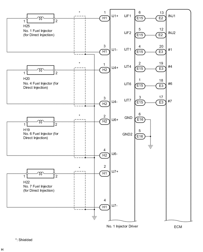
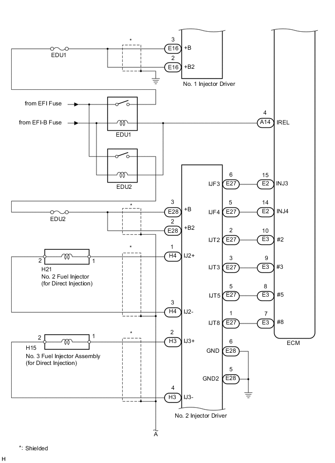
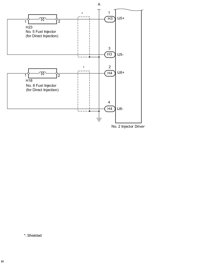
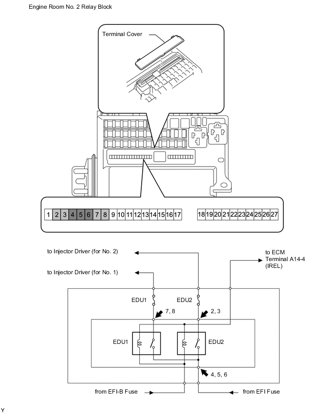
WIRING DIAGRAM
CAUTION / NOTICE / HINT
Tech Tips
Read freeze frame data using the intelligent tester. Freeze frame data records the engine condition when malfunctions are detected. When troubleshooting, freeze frame data can help determine if the vehicle was moving or stationary, if the engine was warmed up or not, if the air-fuel ratio was lean or rich, and other data from the time the malfunction occurred.
PROCEDURE
-
INSPECT INJECTOR DRIVER (POWER SOURCE OF ECU)
-
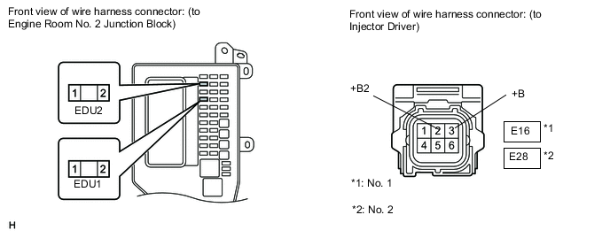
Disconnect the E16 or E28 injector driver (EDU) connector.
Note
Do not disconnect the connectors while the engine is running.
-
Turn the Power switch on (IG).
Note
-
If DTC P062D or P062E is detected, the inspection cannot be performed. Therefore, clear the DTCs, and then turn the power switch on (IG).
-
Do not turn the power switch on (READY) after clearing the DTCs.
-
-
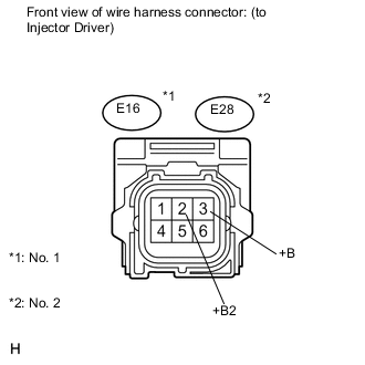
Measure the voltage according to the value(s) in the table below.
Standard voltage Tester Connection Switch Condition Specified Condition E16-3 (+B) - Engine ground Power switch on (IG) 11 to 14 V E16-2 (+B2) - Engine ground Power switch on (IG) 11 to 14 V E28-3 (+B) - Engine ground Power switch on (IG) 11 to 14 V E28-2 (+B2) - Engine ground Power switch on (IG) 11 to 14 V
NG 
CHECK HARNESS AND CONNECTOR (ENGINE ROOM NO. 2 JUNCTION BLOCK - INJECTOR DRIVER) Click here
OK 
-
-
CHECK FOR DTC
-
Turn the power switch off.
-
*1 No. 2 Injector Driver *2 No. 1 Injector Driver Interchange the No. 1 and No. 2 injector drivers.
Note
Do not disconnect and reconnect the connectors with the power switch on (IG), as the injector driver (EDU) may be damaged.
-
Connect the intelligent tester to the DLC3.
-
Turn the power switch on (READY).
-
Turn the tester ON.
-
Clear DTCs Click here.
Note
Before clearing the DTCs, write them down.
-
Enter the following menus: Powertrain / Engine and ECT / DTC.
-
Read DTC.
Result Display (DTC Output) Proceed to DTCs do not change A DTCs change (change in malfunctioning cylinder or EDU code) B
B 
REPLACE INJECTOR DRIVER Click here
A
-
-
INSPECT FUEL INJECTOR (for Direct Injection)
-
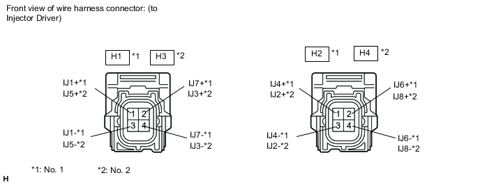
Disconnect the H1 or H2 No. 1 injector driver connector.
-
Disconnect the H3 or H4 No. 2 injector driver connector.
-
Measure the resistance according to the value(s) in the table below.
Standard resistance Tester Connection Condition Specified Condition H1-1 (IJ1+) - H1-3 (IJ1-) 20°C (68°F) 2.01 to 2.43 Ω H1-2 (IJ7+) - H1-4 (IJ7-) 20°C (68°F) 2.01 to 2.43 Ω H3-1 (IJ5+) - H3-3 (IJ5-) 20°C (68°F) 2.01 to 2.43 Ω H3-2 (IJ3+) - H3-4 (IJ3-) 20°C (68°F) 2.01 to 2.43 Ω H2-1 (IJ4+) - H2-3 (IJ4-) 20°C (68°F) 2.01 to 2.43 Ω H2-2 (IJ6+) - H2-4 (IJ6-) 20°C (68°F) 2.01 to 2.43 Ω H4-1 (IJ2+) - H4-3 (IJ2-) 20°C (68°F) 2.01 to 2.43 Ω H4-2 (IJ8+) - H4-4 (IJ8-) 20°C (68°F) 2.01 to 2.43 Ω
NG
INSPECT FUEL INJECTOR (for Direct Injection) Click here
OK
-
-
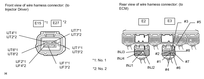
CHECK HARNESS AND CONNECTOR (INJECTOR DRIVER - ECM)
-
Disconnect the E15 or E27 injector driver (EDU) connector.
-
Disconnect the E2 and E3 ECM connectors.
-
Measure the resistance according to the value(s) in the table below.
Standard resistance (Check for open) Tester Connection Condition Specified Condition E15-6 (IJF1) - E2-13 (INJ1) Always Below 1 Ω E15-5 (IJF2) - E2-12 (INJ2) Always Below 1 Ω E27-6 (IJF3) - E2-15 (INJ3) Always Below 1 Ω E27-5 (IJF4) - E2-14 (INJ4) Always Below 1 Ω E15-4 (IJT1) - E3-20 (#1) Always Below 1 Ω E27-2 (IJT2) - E3-10 (#2) Always Below 1 Ω E27-3 (IJT3) - E3-9 (#3) Always Below 1 Ω E15-2 (IJT4) - E3-19 (#4) Always Below 1 Ω E27-4 (IJT5) - E3-8 (#5) Always Below 1 Ω E15-1 (IJT6) - E3-18 (#6) Always Below 1 Ω E15-3 (IJT7) - E3-17 (#7) Always Below 1 Ω E27-1 (IJT8) - E3-7 (#8) Always Below 1 Ω Standard resistance (Check for short) Tester Connection Condition Specified Condition E15-6 (IJF1) or E2-13 (INJ1) - Body ground Always 1 MΩ or higher E15-5 (IJF2) or E2-12 (INJ2) - Body ground Always 1 MΩ or higher E27-6 (IJF3) or E2-15 (INJ3) - Body ground Always 1 MΩ or higher E27-5 (IJF4) or E2-14 (INJ4) - Body ground Always 1 MΩ or higher E15-4 (IJT1) or E3-20 (#1) - Body ground Always 1 MΩ or higher E27-2 (IJT2) or E3-10 (#2) - Body ground Always 1 MΩ or higher E27-3 (IJT3) or E3-9 (#3) - Body ground Always 1 MΩ or higher E15-2 (IJT4) or E3-19 (#4) - Body ground Always 1 MΩ or higher E27-4 (IJT5) or E3-8 (#5) - Body ground Always 1 MΩ or higher E15-1 (IJT6) or E3-18 (#6) - Body ground Always 1 MΩ or higher E15-3 (IJT7) or E3-17 (#7) - Body ground Always 1 MΩ or higher E27-1 (IJT8) or E3-7 (#8) - Body ground Always 1 MΩ or higher
NG
REPAIR OR REPLACE HARNESS OR CONNECTOR
OK
-
-
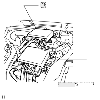
INSPECT ENGINE ROOM NO. 2 JUNCTION BLOCK (EDU1, EDU2 RELAY)
Tech Tips
The EDU1 and EDU2 relay cannot be removed and inspected, as they are part of the engine room No. 2 junction block internal circuit.
-
Remove the terminal cover.
-
Measure the voltage according to the value(s) in the table below.
Standard voltage Tester Connection Condition Specified Condition 4 - Body ground Always 11 to 14 V 5 - Body ground 6 - Body ground 2 - Body ground Power switch on (IG) 3 - Body ground 7 - Body ground 8 - Body ground
NG
REPLACE ENGINE ROOM NO. 2 JUNCTION BLOCK
OK
-
-
CHECK HARNESS AND CONNECTOR (ENGINE ROOM NO. 2 JUNCTION BLOCK - INJECTOR DRIVER)
-
Remove the EDU1 and EDU2 fuses from the engine room No. 2 junction block.
-
Measure the resistance according to the value(s) in the table below.
Standard resistance Tester Connection Condition Specified Condition EDU1 fuse Always Below 1 Ω EDU2 fuse -
Disconnect the E16 or E28 injector driver (EDU) connector.
-
Measure the resistance according to the value(s) in the table below.
Standard resistance (Check for open) Tester Connection Condition Specified Condition EDU1 (2) - E16-3 (+B) Always Below 22 mΩ EDU1 (2) - E16-2 (+B2) Always Below 22 mΩ EDU2 (2) - E28-3 (+B) Always Below 22 mΩ EDU2 (2) - E28-2 (+B2) Always Below 22 mΩ Standard resistance (Check for short) Tester Connection Condition Specified Condition EDU1 (2) or E16-3 (+B) - Body ground Always 10 kΩ or higher EDU1 (2) or E16-2 (+B2) - Body ground Always 10 kΩ or higher EDU2 (2) or E28-3 (+B) - Body ground Always 10 kΩ or higher EDU2 (2) or E28-2 (+B2) - Body ground Always 10 kΩ or higher
OK
REPLACE ENGINE ROOM NO. 2 JUNCTION BLOCK
NG
REPAIR OR REPLACE HARNESS OR CONNECTOR
-
-
INSPECT FUEL INJECTOR (for Direct Injection)
-
Check the resistance of the fuel injector (for Direct Injection) Click here.
OK
REPAIR OR REPLACE HARNESS OR CONNECTOR
NG
REPLACE FUEL INJECTOR (for Direct Injection) Click here
-