WIRELESS DOOR LOCK CONTROL SYSTEM TERMINALS OF ECU
-
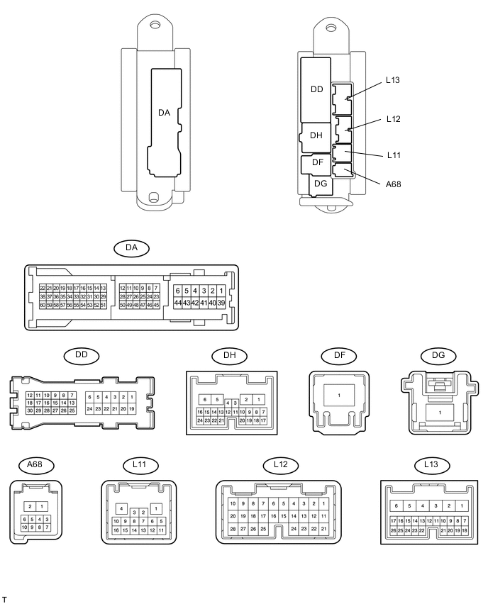
CHECK MAIN BODY ECU (DRIVER SIDE JUNCTION BLOCK)
-
Disconnect the DA, DD, DF, L12 and L13 ECU connectors.
-
Measure the resistance and voltage according to value(s) in the table below.
Terminal No. (Symbols) Wiring Color Terminal Description Condition Specified Condition DA-40 (GND2) - Body ground W-B - Body ground Ground Always Below 1 Ω DF-1 (ACC) - DA-40 (GND2) B - W-B ACC power supply Power switch OFF Below 1 V Power switch ON (ACC) 11 to 14 V DF-1 (IG) - DA-40 (GND2) B - W-B IG power supply Power switch OFF Below 1 V Power switch ON (IG) 11 to 14 V L13-24 (DCTY) - Body ground W - Body ground Driver side door courtesy light switch input Driver side door open Below 1 Ω Driver side door closed 10 kΩ or higher L12-21 (PCTY) - Body ground L - Body ground Passenger side door courtesy light switch input Passenger side door open Below 1 Ω Passenger side door closed 10 kΩ or higher L12-7 (RCTY) - Body ground R - Body ground Rear RH side door courtesy light switch input Rear side door RH open Below 1 Ω Rear side door RH closed 10 kΩ or higher DD-12 (LCTY) - Body ground L - Body ground Rear LH side door courtesy light switch input Rear side door LH open Below 1 Ω Rear side door LH closed 10 kΩ or higher -
Reconnect the DA, DD, DF, L12 and L3 ECU connectors.
-
Measure the voltage according to the value(s) in the table below.
Terminal No. (Symbols) Wiring Color Terminal Description Condition Specified Condition L11-14 (HAZ) - Body ground BE - Body ground Turn signal light drive Hazard warning signal switch ON Pulse generation Hazard warning signal switch OFF Below 1 V -
-
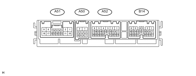
CHECK FRONT MULTIPLEX NETWORK LIGHT ECU (FRONT CONTROLLER)
-
Disconnect the A50 and A52 ECU connectors.
-
Measure the resistance and voltage according to the value(s) in the table below.
Terminal No. (Symbols) Wiring Color Terminal Description Condition Specified Condition A50-2 (E) - Body ground W-B - Body ground Ground Always Below 1 Ω A52-1 (BATB) - Body ground P - Body ground Power supply Always 11 to 14 V A52-5 (ALTB) - Body ground L - Body ground Power supply Always 11 to 14 V -
Reconnect the A50 and A52 ECU connectors.
-
Measure the voltage according to the value(s) in the table below.
Terminal No. (Symbols) Wiring Color Terminal Description Condition Specified Condition A52-14 (BZR)* - Body ground B - Body ground Wireless door lock buzzer output Wireless door lock buzzer ON 11 to 14 V Wireless door lock buzzer OFF Below 1 V Tech Tips
*: Except Europe and China
-
-
CHECK LUGGAGE CLOSER MOTOR ASSEMBLY

-
Disconnect the S43 ECU connector.
-
Measure the resistance and voltage according to the value(s) in the table below.
Terminal No. (Symbols) Wiring Color Terminal Description Condition Specified Condition S43-11 (GND) - Body ground W-B - Body ground Ground Always Below 1 Ω S43-10 (ECUB) - S43-11 (GND) B - W-B Power supply Always 11 to 14 V S43-12 (B) - S43-11 (GND) G - W-B Power supply Always 11 to 14 V -
Reconnect the S43 ECU connector.
-
Measure the voltage according to the value(s) in the table below.
Terminal No. (Symbols) Wiring Color Terminal Description Condition Specified Condition S43-22 (LCTY) - S43-11 (GND) G - W-B Luggage compartment door courtesy light switch output Luggage compartment door open Pulse generation Luggage compartment door closed Below 1 V -
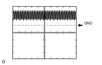
Using an oscilloscope, check the waveform.
Waveform (Reference) Item Content Terminal No. (Symbols) S43-22 (LCTY) - S43-11 (GND) Tool Setting 5 V/DIV. , 20ms/DIV. Condition Luggage compartment door open
-
-
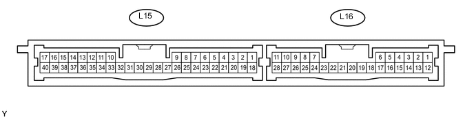
CHECK CERTIFICATION ECU
-
Disconnect the L15 and L16 ECU connectors.
-
Measure the resistance and voltage according to the value(s) in the table below.
Terminal No. (Symbols) Wiring Color Terminal Description Condition Specified Condition L15-17 (E) - Body ground W-B - Body ground Ground Always Below 1 Ω L15-1 (+B1) - L15-17 (E) L - W-B Battery power supply Always 11 to 14 V L15-18 (IG) - L15-17 (E) L - W-B IG power supply Power switch ON (IG) 11 to 14 V Power switch OFF Below 1 V -
Reconnect the L15 and L16 ECU connectors.
-
Measure the voltage according to the value(s) in the table below.
Terminal No. (Symbols) Wiring Color Terminal Description Condition Specified Condition L15-39 (RSSI) - L15-17 (E) W - W-B Door control receiver electric wave existence signal Power switch OFF, all doors closed, and transmitter switch not pressed 11 to 14 V Power switch OFF, all doors closed, and transmitter switch pressed Below 2 V L15-38 (RDA) - L15-17 (E) R - W-B Door control receiver data input signal Power switch OFF, all doors closed, and transmitter switch not pressed Below 2 V Power switch OFF, all doors closed, and transmitter switch pressed 11 to 14 V L15-37 (ASEL) - L15-17 (E) L - W-B Door control receiver select signal Power switch OFF, all doors closed, and luggage compartment door closed Below 1 V Power switch OFF, all doors closed, and luggage compartment door open 4.6 to 5.4 V L15-29 (RCO) - L15-17 (E) G - W-B Door control receiver power source Power switch OFF, all doors closed, and transmitter switch pressed 4.6 to 5.4 V Power switch OFF, all doors closed, and transmitter switch not pressed Below 1 V
-