WIPER AND WASHER SYSTEM ECU Power Source Circuit
DESCRIPTION
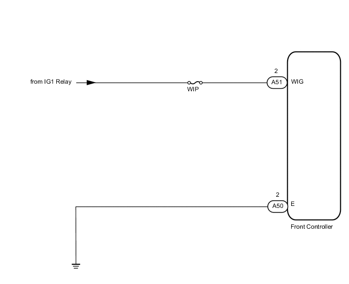
This circuit provides power to the front wiper motor and operates the front controller.
WIRING DIAGRAM
PROCEDURE
-
INSPECT FUSE (WIP)
-
Remove the WIP fuse from the engine room No. 2 relay block.
-
Measure the resistance according to the value(s) in the table below.
Standard resistance Tester Connection Condition Specified Condition WIP fuse Always Below 1 Ω
NG 
REPLACE FUSE
OK 
-
-
CHECK HARNESS AND CONNECTOR (FRONT CONTROLLER - BATTERY)
-
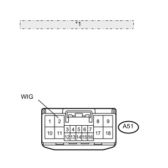
*1 Front view of wire harness connector: (to Front Controller) Disconnect the A51 front controller connector.
-
Measure the voltage according to the value(s) in the table below.
Standard voltage Tester Connection Switch Condition Specified Condition A51-2 (WIG) - Body ground Power switch ON (IG) 11 to 14 V A51-2 (WIG) - Body ground Power switch OFF Below 1 V
NG
REPAIR OR REPLACE HARNESS OR CONNECTOR
OK
-
-
CHECK HARNESS AND CONNECTOR (FRONT CONTROLLER - BODY GROUND)
-
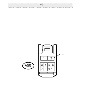
*1 Front view of wire harness connector: (to Front Controller) Disconnect the A50 ECU connectors.
-
Measure the resistance according to the value(s) in the table below.
Standard resistance Tester Connection Condition Specified Condition A50-2 - Body ground Always Below 1 Ω
OK
PROCEED TO NEXT CIRCUIT INSPECTION SHOWN IN PROBLEM SYMPTOMS TABLE Click here
NG
REPAIR OR REPLACE HARNESS OR CONNECTOR
-