ROOM LIGHT ASSEMBLY(for Front) ON-VEHICLE INSPECTION
PROCEDURE
-
INSPECT MAP LIGHT ASSEMBLY
-
Remove the map light assembly with its connectors connected.
-
Measure the voltage according to the value(s) in the table below.
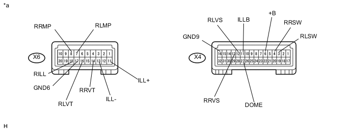
Text in Illustration *a Component with harness connected
(Map Light Assembly)
- - Standard Voltage Tester Connection Switch Condition Specified Condition X4-3 (RLSW) - X4-16 (GND9) Rear spot light RH switch OFF Below 1 V Rear spot light RH switch ON 11 to 14 V X4-4 (RRSW) - X4-16 (GND9) Rear spot light LH switch OFF Below 1 V Rear spot light LH switch ON 11 to 14 V X4-6 (+B) - X4-16 (GND9) Always 11 to 14 V X4-11 (ILLB) - X4-16 (GND9) Always 11 to 14 V X4-12 (RLVS) - X4-16 (GND9) Rear vanity light LH switch OFF Below 1 V Rear vanity light LH switch ON 11 to 14 V X4-13 (RRVS) - X4-16 (GND9) Rear vanity light RH switch OFF Below 1 V Rear vanity light RH switch ON 11 to 14 V X4-27 (DOME) - X4-16 (GND9) Always 11 to 14 V X6-7 (RLMP) - X4-16 (GND9) Always 11 to 14 V X6-8 (RRMP) - X4-16 (GND9) Always 11 to 14 V X6-11 (ILL+) - X4-16 (GND9) Power switch on (ACC) 11 to 14 V X6-13 (ILL-) - X4-16 (GND9) Headlight dimmer switch OFF 11 to 14 V Headlight dimmer switch TAIL Below 1 V X6-14 (RRVT) - X4-16 (GND9) Rear vanity light RH switch OFF 11 to 14 V Rear vanity light RH switch ON Below 1 V X6-16 (RLVT) - X4-16 (GND9) Rear vanity light LH switch OFF 11 to 14 V Rear vanity light LH switch ON Below 1 V X6-18 (RILL) - X4-16 (GND9) Rear dome light OFF 11 to 14 V Rear dome light ON Below 1 V If the result is not as specified, replace the map light assembly.
-
Measure the resistance according to the value(s) in the table below.
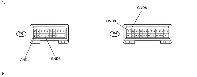
Text in Illustration *a Component with harness connected
(Map Light Assembly)
- - Standard Resistance Tester Connection Condition Specified Condition X4-15 (GND6) - Body ground Always Below 1 Ω X4-16 (GND9) - Body ground Always Below 1 Ω X6-17 (GND6) - Body ground Always Below 1 Ω X6-20 (GND4) - Body ground Always Below 1 Ω If the result is not as specified, replace the map light assembly.
-