LIGHTING SYSTEM Automatic Light Control Function does not Operate
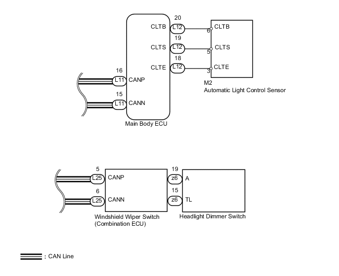
WIRING DIAGRAM
CAUTION / NOTICE / HINT
Note
First perform the communication function inspections in HOW TO PROCEED WITH TROUBLESHOOTING to confirm that there are no CAN communication malfunctions before troubleshooting this symptom.
PROCEDURE
-
READ VALUE USING GTS (AUTOMATIC LIGHT CONTROL SENSOR)
-
Using the GTS, read the Data List.
Main Body Tester Display Measurement Item / Range Normal Condition Diagnostic Note Illumination Rate Info Condition of automatic light control sensor/0 to 2162.65 ms Condition value will be displayed - OK Condition sign can be displayed.
NG 
CHECK HARNESS AND CONNECTOR (MAIN BODY ECU - AUTOMATIC LIGHT CONTROL SENSOR AND BODY GROUND) Click here
OK 
-
-
READ VALUE USING GTS (HEADLIGHT DIMMER SWITCH)
-
Using the GTS, read the Data List.
Combination Switch Tester Display Measurement Item / Range Normal Condition Diagnostic Note Light Auto Switch Headlight dimmer switch signal (AUTO position) / ON or OFF ON: Headlight dimmer switch AUTO position
OFF: Headlight dimmer switch OFF
- OK Condition sign can be displayed.
NG 
REPLACE MAIN BODY ECU
OK
-
-
CHECK WINDSHIELD WIPER SWITCH (OPERATION)
-
Temporarily replace the windshield wiper switch with a new or normally functioning one Click here.
-
Check the windshield wiper switch operation.
OK Windshield wiper switch operation is normal.
OK
END (REPLACE WINDSHIELD WIPER SWITCH) Click here
NG
REPLACE MAIN BODY ECU
-
-
CHECK HARNESS AND CONNECTOR (MAIN BODY ECU - AUTOMATIC LIGHT CONTROL SENSOR AND BODY GROUND)
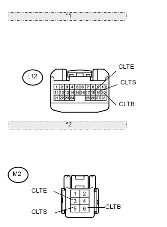
*1 Front view of wire harness connector: (to Main Body ECU) *2 Front view of wire harness connector: (to Automatic Light Control Sensor)
-
Disconnect the L12 ECU connector.
-
Disconnect the M2 sensor connector.
-
Measure the resistance according to the value(s) in the table below.
Standard resistance Tester Connection Condition Specified Condition L12-20 (CLTB) - M2-6 (CLTB) Always Below 1 Ω L12-19 (CLTS) - M2-5 (CLTS) Always Below 1 Ω L12-18 (CLTE) - M2-3 (CLTE) Always Below 1 Ω L12-20 (CLTB) - Body ground Always 10 kΩ or higher L12-19 (CLTS) - Body ground Always 10 kΩ or higher L12-18 (CLTE) - Body ground Always 10 kΩ or higher
NG
REPAIR OR REPLACE HARNESS OR CONNECTOR
OK
-
-
CHECK MAIN BODY ECU (CLTB VOLTAGE)
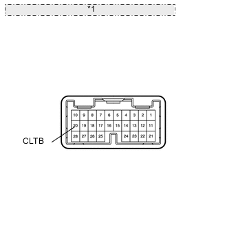
*1 Component without harness connected: (Main Body ECU)
-
Disconnect the L12 ECU connector.
-
Measure the voltage according to the value(s) in the table below.
Standard voltage Tester Connection Switch Condition Specified Condition 20 (CLTB) - Body ground Power switch ON (IG) 11 to 14 V
OK
REPLACE AUTOMATIC LIGHT CONTROL SENSOR Click here
NG
REPLACE MAIN BODY ECU
-