LIGHTING SYSTEM Driver Side Instrument Panel Illumination does not Turn On
WIRING DIAGRAM
Refer to the wiring diagram for "Instrument Panel Illumination does not Turn On" Click here.
CAUTION / NOTICE / HINT
Note
Inspect the fuses for circuits related to this system before performing the following inspection procedure.
PROCEDURE
-
CHECK CONNECTOR CONNECTION CONDITION (NO. 2 INSTRUMENT PANEL GARNISH [DRIVER SIDE INSTRUMENT PANEL ILLUMINATION])
-
Check the connection of connector of the No. 2 instrument panel garnish (driver side instrument panel illumination).
OK The connector is connected securely and there are no contact problems.
NG 
CONNECT SECURELY
OK 
-
-
CHECK CONNECTOR CONNECTION CONDITION (NO. 1 INSTRUMENT PANEL GARNISH [PASSENGER SIDE INSTRUMENT PANEL ILLUMINATION])
-
Check the connection of connector of the No. 1 instrument panel garnish (passenger side instrument panel illumination).
OK The connector is connected securely and there are no contact problems.
NG
CONNECT SECURELY
OK
-
-
CHECK HARNESS AND CONNECTOR (NO. 1 INSTRUMENT PANEL GARNISH [PASSENGER SIDE INSTRUMENT PANEL ILLUMINATION] - NO. 2 INSTRUMENT PANEL GARNISH [DRIVER SIDE INSTRUMENT PANEL ILLUMINATION]
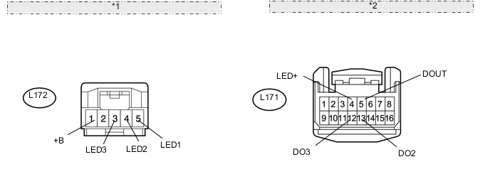
*1 Front view of wire harness connector: (to No. 2 Instrument Panel Garnish [Driver Side Instrument Panel Illumination]) *2 Front view of wire harness connector: (to No. 1 Instrument Panel Garnish [Passenger Side Instrument Panel Illumination])
-
Disconnect the L171 No. 1 instrument panel garnish (passenger side instrument panel illumination) connector.
-
Disconnect the L172 No. 2 instrument panel garnish (driver side instrument panel illumination) connector.
-
Measure the resistance according to the value(s) in the table below.
Standard Resistance Tester Connection Condition Specified Condition L172-1 (+B) - L171-4 (LED+) Always Below 1 Ω L172-1 (+B) - Body ground Always 10 kΩ or higher L172-5 (LED1) - L171-5 (DOUT) Always Below 1 Ω L172-5 (LED1) - Body ground Always 10 kΩ or higher L172-4 (LED2) - L171-13 (DO2) Always Below 1 Ω L172-4 (LED2) - Body ground Always 10 kΩ or higher L172-3 (LED3) - L171-12 (DO3) Always Below 1 Ω L172-3 (LED3) - Body ground Always 10 kΩ or higher
NG
REPAIR OR REPLACE HARNESS OR CONNECTOR
OK
-
-
CHECK NO. 2 INSTRUMENT PANEL GARNISH SUB-ASSEMBLY (DRIVER SIDE INSTRUMENT PANEL ILLUMINATION)
-
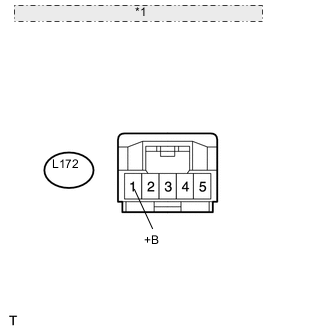
*1 Front view of wire harness connector: (to No. 2 Instrument Panel Garnish [Driver Side Instrument Panel Illumination]) Disconnect the L172 No. 2 instrument panel garnish (driver side instrument panel illumination) connector.
-
Measure the voltage according to the value(s) in the table below.
Standard Voltage Tester Connection Condition Specified Condition L172-1 (+B) - Body ground Instrument panel illumination is off (when not in sleep mode [20 minutes within opening any door]) 7.5 to 8.5 V
NG
REPLACE NO. 1 INSTRUMENT PANEL GARNISH SUB-ASSEMBLY (PASSENGER SIDE INSTRUMENT PANEL ILLUMINATION) Click here
OK
-
-
CHECK WAVEFORM
-
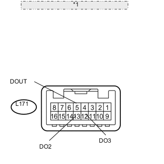
*1 Component with harness connected: (to No. 1 Instrument Panel Garnish [Passenger Side Instrument Panel Illumination]) Connect an oscilloscope to the No. 1 instrument panel garnish (passenger side instrument panel illumination) connector.
-
Using an oscilloscope, check the signal waveform of the ECU.
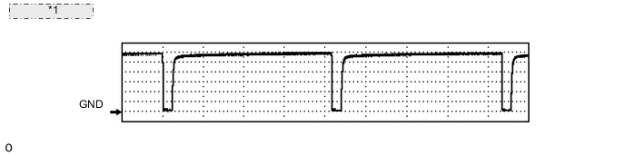
*1 Waveform example Item Content Terminal No. (Symbol)
-
L171-5 (DOUT) - Body ground
-
L171-13 (DO2) - Body ground
-
L171-12 (DO3) - Body ground
Tool Setting 1 V/DIV., 2 ms/DIV. Condition Power switch on (IG), instrument panel illumination being dimmed after shift position moved from P OK The waveform is output as shown in the illustration. -
OK
REPLACE NO. 2 INSTRUMENT PANEL GARNISH SUB-ASSEMBLY (DRIVER SIDE INSTRUMENT PANEL ILLUMINATION) Click here
NG
REPLACE NO. 1 INSTRUMENT PANEL GARNISH SUB-ASSEMBLY (PASSENGER SIDE INSTRUMENT PANEL ILLUMINATION) Click here
-