LIGHTING SYSTEM Instrument Panel Illumination does not Turn On Properly
WIRING DIAGRAM
Refer to the wiring diagram for "Instrument Panel Illumination does not Turn On" Click here
PROCEDURE
-
READ VALUE USING GTS (INSTRUMENT PANEL ILLUMINATION)
-
Using the GTS, read the Data List Click here.
Main Body Tester Display Measurement Item/Display Normal Condition Diagnostic Note Instrument Panel Illumination Instrument panel illumination condition/ON or OFF ON: Instrument panel illumination is flowing
OFF: Instrument panel illumination is not flowing
- Result Result Proceed to Condition sign can not be displayed. A Condition sign can be displayed. B
B 
CHECK CONNECTOR CONNECTION CONDITION (NO. 1 INSTRUMENT PANEL GARNISH [PASSENGER SIDE INSTRUMENT PANEL ILLUMINATION]) Click here
A 
-
-
CHECK CONNECTOR CONNECTION CONDITION (NO. 1 INSTRUMENT PANEL GARNISH [PASSENGER SIDE INSTRUMENT PANEL ILLUMINATION])
-
Check the connection of connector of the No. 1 instrument panel garnish (passenger side instrument panel illumination)
OK The connector is connected securely and there are no contact problems.
NG 
CONNECT SECURELY
OK
-
-
CHECK CONNECTOR CONNECTION CONDITION (MAIN BODY ECU)
-
Check the connection of connector of the main body ECU.
OK The connector is connected securely and there are no contact problems.
NG
CONNECT SECURELY
OK
-
-
CHECK HARNESS AND CONNECTOR (MAIN BODY ECU - NO. 1 INSTRUMENT PANEL GARNISH [PASSENGER SIDE ILLUMINATION])
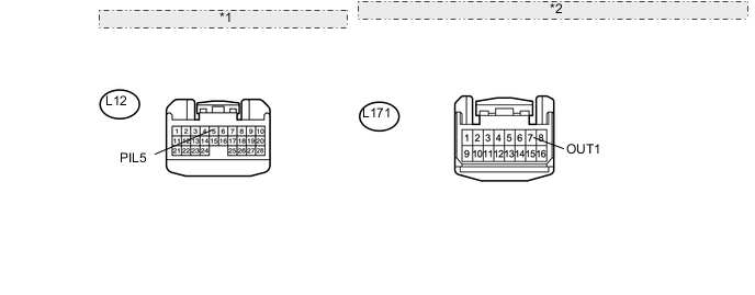
*1 Front view of wire harness connector: (to Main Body ECU) *2 Front view of wire harness connector: (to No. 1 Instrument Panel Garnish [Passenger Side Instrument Panel Illumination])
-
Disconnect the L12 main body ECU connector.
-
Disconnect the L171 No. 1 instrument panel garnish (passenger side instrument panel illumination) connector.
-
Measure the resistance according to the value(s) in the table below.
Standard Resistance Tester Connection Condition Specified Condition L171-7 (OUT1) - L12-5 (PIL5) Always Below 1 Ω L171-7 (OUT1) - Body ground Always 10 kΩ or higher
NG
REPAIR OR REPLACE HARNESS OR CONNECTOR
OK
-
-
CHECK NO. 1 INSTRUMENT PANEL GARNISH SUB-ASSEMBLY (PASSENGER SIDE INSTRUMENT PANEL ILLUMINATION)
-
Temporarily replace the No. 1 instrument panel garnish (passenger side instrument panel illumination) with a new or normally functioning one Click here.
-
Operate the instrument panel illumination and check the illumination condition.
OK Instrument panel illumination operation is normal
OK
END (NO. 1 INSTRUMENT PANEL GARNISH [PASSENGER SIDE INSTRUMENT PANEL ILLUMINATION] WAS DEFECTIVE)
NG
REPLACE MAIN BODY ECU (DRIVER SIDE JUNCTION BLOCK ASSEMBLY)
-
-
CHECK CONNECTOR CONNECTION CONDITION (NO. 1 INSTRUMENT PANEL GARNISH [PASSENGER SIDE INSTRUMENT PANEL ILLUMINATION])
-
Check the connection of connector of the No. 1 instrument panel garnish (passenger side instrument panel illumination)
OK The connector is connected securely and there are no contact problems.
NG
CONNECT SECURELY
OK
-
-
CHECK CONNECTOR CONNECTION CONDITION (MAIN BODY ECU)
-
Check the connection of connector of the main body ECU.
OK The connector is connected securely and there are no contact problems.
NG
CONNECT SECURELY
OK
-
-
CHECK HARNESS AND CONNECTOR (MAIN BODY ECU - NO. 1 INSTRUMENT PANEL GARNISH [PASSENGER SIDE ILLUMINATION])
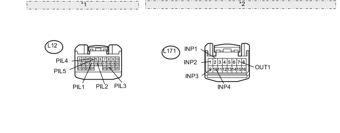
*1 Front view of wire harness connector: (to Main Body ECU) *2 Front view of wire harness connector: (to No. 1 Instrument Panel Garnish [Passenger Side Instrument Panel Illumination])
-
Disconnect the L12 main body ECU connector.
-
Disconnect the L171 No. 1 instrument panel garnish (passenger side instrument panel illumination) connector.
-
Measure the resistance according to the value(s) in the table below.
Standard Resistance Tester Connection Condition Specified Condition L171-2 (INP1) - L12-14 (PIL1) Always Below 1 Ω L171-2 (INP1) - Body ground Always 10 kΩ or higher L171-1 (INP2) - L12-15 (PIL2) Always Below 1 Ω L171-1 (INP2) - Body ground Always 10 kΩ or higher L171-9 (INP3) - L12-26 (PIL3) Always Below 1 Ω L171-9 (INP3) - Body ground Always 10 kΩ or higher L171-10 (INP4) - L12-4 (PIL4) Always Below 1 Ω L171-10 (INP4) - Body ground Always 10 kΩ or higher L171-7 (OUT1) - L12-5 (PIL5) Always Below 1 Ω L171-7 (OUT1) - Body ground Always 10 kΩ or higher
NG
REPAIR OR REPLACE HARNESS OR CONNECTOR
OK
-
-
CHECK WAVEFORM
-
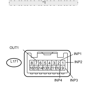
*1 Component with harness connected: (to No. 1 Instrument Panel Garnish [Passenger Side Instrument Panel Illumination]) Using an oscilloscope, measure the waveform with the connector connected, and check that there is no applied noise.
-
INP1
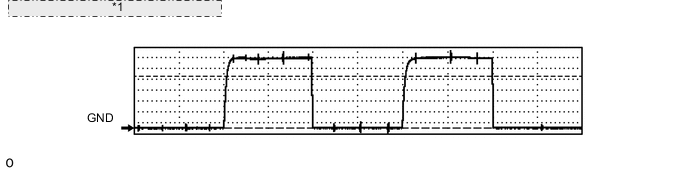
*1 Waveform example (with applied noise) Item Content Terminal No. (Symbol) L171-2 (INP1) - Body ground Tool Setting 2 V/DIV., 5 ms/DIV. Condition Instrument panel illumination is off (when not in sleep mode [20 minutes within opening any door]) -
INP2
*1 Waveform example (with applied noise) Item Content Terminal No. (Symbol) L171-1 (INP2) - Body ground Tool Setting 2 V/DIV., 5 ms/DIV. Condition Instrument panel illumination is off (when not in sleep mode [20 minutes within opening any door]) -
INP3
*1 Waveform example (with applied noise) Item Content Terminal No. (Symbol) L171-9 (INP3) - Body ground Tool Setting 2 V/DIV., 5 ms/DIV. Condition Instrument panel illumination is off (when not in sleep mode [20 minutes within opening any door]) -
INP4
*1 Waveform example (with applied noise) Item Content Terminal No. (Symbol) L171-10 (INP4) - Body ground Tool Setting 2 V/DIV., 5 ms/DIV. Condition Instrument panel illumination is off (when not in sleep mode [20 minutes within opening any door]) -
OUT1
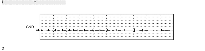
*1 Waveform example (with applied noise) Item Content Terminal No. (Symbol) L171-7 (OUT1) - Body ground Tool Setting 5 V/DIV., 5 ms/DIV. Condition Instrument panel illumination is off (when not in sleep mode [20 minutes within opening any door]) OK The output waveform does not resemble the waveform with applied noise shown in the illustration
-
NG
CHECK RADIO WAVE CONDITION Click here
OK
-
-
CHECK NO. 1 INSTRUMENT PANEL GARNISH SUB-ASSEMBLY (PASSENGER SIDE INSTRUMENT PANEL ILLUMINATION)
-
Temporarily replace the No. 1 instrument panel garnish (passenger side instrument panel illumination) with a new or normally functioning one Click here.
-
Operate the instrument panel illumination and check the illumination condition.
OK Instrument panel illumination operation is normal
OK
END (NO. 1 INSTRUMENT PANEL GARNISH [PASSENGER SIDE INSTRUMENT PANEL ILLUMINATION] WAS DEFECTIVE)
NG
REPLACE MAIN BODY ECU (DRIVER SIDE JUNCTION BLOCK ASSEMBLY)
-
-
CHECK RADIO WAVE CONDITION
-
Move any devices that output radio waves away from the instrument panel and check that the instrument panel illumination lights turn on normally.
OK Instrument panel illumination operation is normal
OK
END (APPLIED NOISE)
NG
-
-
CHECK NO. 1 INSTRUMENT PANEL GARNISH SUB-ASSEMBLY (PASSENGER SIDE INSTRUMENT PANEL ILLUMINATION)
-
Temporarily replace the No. 1 instrument panel garnish (passenger side instrument panel illumination) with a new or normally functioning one Click here.
-
Operate the instrument panel illumination and check the illumination condition.
OK Instrument panel illumination operation is normal
OK
END (NO. 1 INSTRUMENT PANEL GARNISH [PASSENGER SIDE INSTRUMENT PANEL ILLUMINATION] WAS DEFECTIVE)
NG
REPLACE MAIN BODY ECU (DRIVER SIDE JUNCTION BLOCK ASSEMBLY)
-