LIGHTING SYSTEM Instrument Panel Illumination does not Turn On
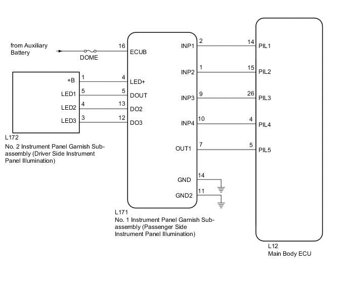
WIRING DIAGRAM
CAUTION / NOTICE / HINT
Note
-
Inspect the fuses for circuits related to this system before performing the following inspection procedure.
-
Before troubleshooting, check that the customization setting of the instrument panel illumination is not set to off.
PROCEDURE
-
PERFORM ACTIVE TEST USING GTS (INSTRUMENT PANEL ILLUMINATION)
-
Using the GTS, perform the Active Test Click here.
OK Instrument panel illumination condition can be switched by Active Test. Main Body Tester Display Test Part Control Range Instrument Panel Illumination Instrument panel illumination operation OFF-ON Result Result Proceed to All of the instrument panel illumination lights do not come on A All of the instrument panel illumination lights come on B Some or all of the passenger side instrument panel illumination lights do not come on C Some or all of the driver side instrument panel illumination lights do not come on D
B 
READ VALUE USING GTS (INSTRUMENT PANEL ILLUMINATION) Click here
C 
REPLACE NO. 1 INSTRUMENT PANEL GARNISH SUB-ASSEMBLY (PASSENGER SIDE INSTRUMENT PANEL ILLUMINATION) Click here
D
PROCEED TO NEXT SUSPECTED AREA SHOWN IN PROBLEM SYMPTOMS TABLE Click here
A 
-
-
CHECK CONNECTOR CONNECTION CONDITION (NO. 1 INSTRUMENT PANEL GARNISH [PASSENGER SIDE INSTRUMENT PANEL ILLUMINATION])
-
Check the connection of connector of the No. 1 instrument panel garnish (passenger side instrument panel illumination)
OK The connector is connected securely and there are no contact problems.
NG
CONNECT SECURELY
OK
-
-
CHECK CONNECTOR CONNECTION CONDITION (MAIN BODY ECU)
-
Check the connection of connector of the main body ECU.
OK The connector is connected securely and there are no contact problems.
NG
CONNECT SECURELY
OK
-
-
CHECK HARNESS AND CONNECTOR (NO. 1 INSTRUMENT PANEL GARNISH [PASSENGER SIDE ILLUMINATION] - MAIN BODY ECU)
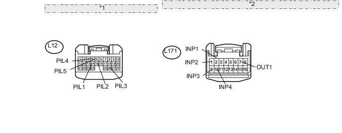
*1 Front view of wire harness connector: (to Main Body ECU) *2 Front view of wire harness connector: (to No. 1 Instrument Panel Garnish [Passenger Side Instrument Panel Illumination])
-
Disconnect the L12 main body ECU connector.
-
Disconnect the L171 No. 1 instrument panel garnish (passenger side instrument panel illumination) connector.
-
Measure the resistance according to the value(s) in the table below.
Standard Resistance Tester Connection Condition Specified Condition L171-2 (INP1) - L12-14 (PIL1) Always Below 1 Ω L171-2 (INP1) - Body ground Always 10 kΩ or higher L171-1 (INP2) - L12-15 (PIL2) Always Below 1 Ω L171-1 (INP2) - Body ground Always 10 kΩ or higher L171-9 (INP3) - L12-26 (PIL3) Always Below 1 Ω L171-9 (INP3) - Body ground Always 10 kΩ or higher L171-10 (INP4) - L12-4 (PIL4) Always Below 1 Ω L171-10 (INP4) - Body ground Always 10 kΩ or higher L171-7 (OUT1) - L12-5 (PIL5) Always Below 1 Ω L171-7 (OUT1) - Body ground Always 10 kΩ or higher
NG
REPAIR OR REPLACE HARNESS OR CONNECTOR
OK
-
-
CHECK HARNESS AND CONNECTOR (NO. 1 INSTRUMENT PANEL GARNISH [PASSENGER SIDE INSTRUMENT PANEL ILLUMINATION] - BATTERY AND BODY GROUND)
-
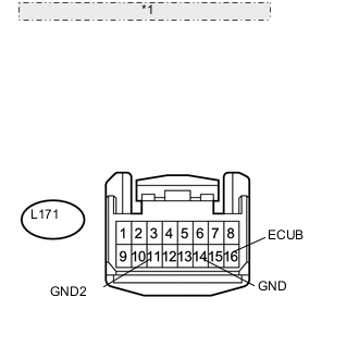
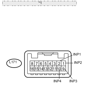
*1 Front view of wire harness connector: (to No. 1 Instrument Panel Garnish [Passenger Side Instrument Panel Illumination]) Disconnect the L171 No. 1 instrument panel garnish (passenger side instrument panel illumination) connector.
-
Measure the voltage according to the value(s) in the table below.
Standard Voltage Tester Connection Condition Specified Condition L171-16 (ECUB) - Body ground Always 11 to 14 V -
Measure the resistance according to the value(s) in the table below.
Standard Resistance Tester Connection Condition Specified Condition L171-14 (GND) - Body ground Always Below 1 Ω L171-11 (GND2) - Body ground Always Below 1 Ω
NG
REPAIR OR REPLACE HARNESS OR CONNECTOR
OK
-
-
CHECK WAVEFORM
-
*1 Component with harness connected: (to No. 1 Instrument Panel Garnish [Passenger Side Instrument Panel Illumination]) Connect an oscilloscope to the No. 1 instrument panel garnish (passenger side instrument panel illumination) connector.
-
Using an oscilloscope, check the signal waveform of the ECU.
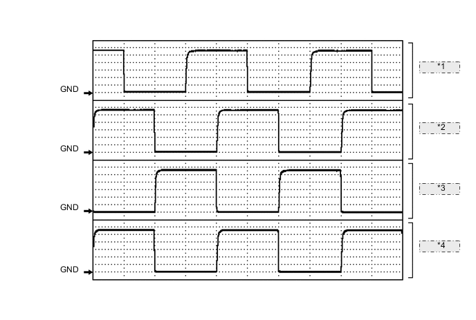
*1 Waveform 1 *2 Waveform 2 *3 Waveform 3 *4 Waveform 4 Waveform 1 Item Content Terminal No. (Symbol) L171-2 (INP1) - Body ground Tool Setting 2 V/DIV., 5 ms/DIV. Condition Instrument panel illumination is off (when not in sleep mode [20 minutes within opening any door]) Waveform 2 Item Content Terminal No. (Symbol) L171-1 (INP2) - Body ground Tool Setting 2 V/DIV., 5 ms/DIV. Condition Instrument panel illumination is off (when not in sleep mode [20 minutes within opening any door]) Waveform 3 Item Content Terminal No. (Symbol) L171-9 (INP3) - Body ground Tool Setting 2 V/DIV., 5 ms/DIV. Condition Instrument panel illumination is off (when not in sleep mode [20 minutes within opening any door]) Waveform 4 Item Content Terminal No. (Symbol) L171-10 (INP4) - Body ground Tool Setting 2 V/DIV., 5 ms/DIV. Condition Instrument panel illumination is off (when not in sleep mode [20 minutes within opening any door]) OK The waveform is output as shown in the illustration.
OK
REPLACE NO. 1 INSTRUMENT PANEL GARNISH SUB-ASSEMBLY (PASSENGER SIDE INSTRUMENT PANEL ILLUMINATION) Click here
NG
-
-
CHECK MAIN BODY ECU (DRIVER SIDE JUNCTION BLOCK ASSEMBLY)
-
Temporarily replace the main body ECU with a new or normally functioning one.
-
Operate the instrument panel illumination and check the illumination condition.
OK Instrument panel illumination operation is normal
OK
END (MAIN BODY ECU WAS DEFECTIVE)
NG
REPLACE NO. 1 INSTRUMENT PANEL GARNISH SUB-ASSEMBLY (PASSENGER SIDE INSTRUMENT PANEL ILLUMINATION) Click here
-
-
READ VALUE USING GTS (INSTRUMENT PANEL ILLUMINATION)
-
Using the GTS, read the Data List Click here.
Main Body Tester Display Measurement Item/Display Normal Condition Diagnostic Note Instrument Panel Illumination Instrument panel illumination condition/ON or OFF ON: Instrument panel illumination is flowing
OFF: Instrument panel illumination is not flowing
- Result Result Proceed to Data List always displays "ON" A Other than above B
B
REPLACE MAIN BODY ECU (DRIVER SIDE JUNCTION BLOCK ASSEMBLY)
A
-
-
CHECK CONNECTOR CONNECTION CONDITION (NO. 1 INSTRUMENT PANEL GARNISH [PASSENGER SIDE INSTRUMENT PANEL ILLUMINATION])
-
Check the connection of connector of the No. 1 instrument panel garnish (passenger side instrument panel illumination)
OK The connector is connected securely and there are no contact problems.
NG
CONNECT SECURELY
OK
-
-
CHECK CONNECTOR CONNECTION CONDITION (MAIN BODY ECU)
-
Check the connection of connector of the main body ECU.
OK The connector is connected securely and there are no contact problems.
NG
CONNECT SECURELY
OK
-
-
CHECK HARNESS AND CONNECTOR (NO. 1 INSTRUMENT PANEL GARNISH [PASSENGER SIDE ILLUMINATION] - MAIN BODY ECU)
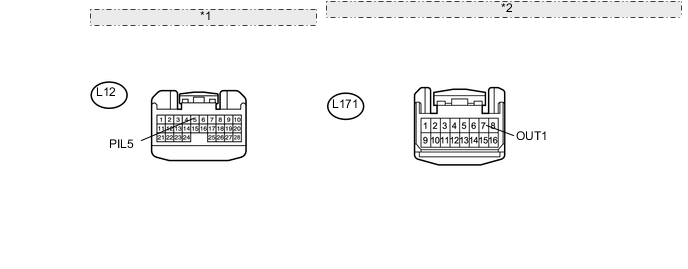
*1 Front view of wire harness connector: (to Main Body ECU) *2 Front view of wire harness connector: (to No. 1 Instrument Panel Garnish [Passenger Side Instrument Panel Illumination])
-
Disconnect the L12 main body ECU connector.
-
Disconnect the L171 No. 1 instrument panel garnish (passenger side instrument panel illumination) connector.
-
Measure the resistance according to the value(s) in the table below.
Standard Resistance Tester Connection Condition Specified Condition L171-7 (OUT1) - L12-5 (PIL5) Always Below 1 Ω L171-7 (OUT1) - Body ground Always 10 kΩ or higher
NG
REPAIR OR REPLACE HARNESS OR CONNECTOR
OK
-
-
CHECK NO. 1 INSTRUMENT PANEL GARNISH SUB-ASSEMBLY (PASSENGER SIDE INSTRUMENT PANEL ILLUMINATION)
-
Temporarily replace the No. 1 instrument panel garnish (passenger side instrument panel illumination) with a new or normally functioning one Click here.
-
Operate the instrument panel illumination and check the illumination condition.
OK Instrument panel illumination operation is normal
OK
END (NO. 1 INSTRUMENT PANEL GARNISH [PASSENGER SIDE INSTRUMENT PANEL ILLUMINATION] WAS DEFECTIVE)
NG
REPLACE MAIN BODY ECU (DRIVER SIDE JUNCTION BLOCK ASSEMBLY)
-