LIGHTING SYSTEM Door Courtesy Light does not Illuminate
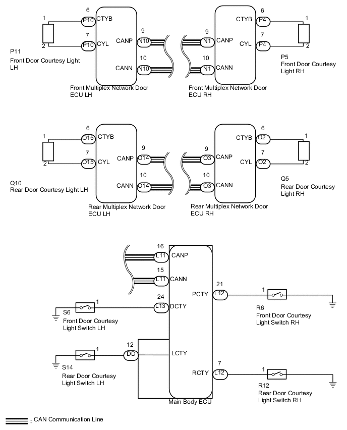
WIRING DIAGRAM
CAUTION / NOTICE / HINT
Note
First perform the communication function inspections in HOW TO PROCEED WITH TROUBLESHOOTING to confirm that there are no CAN communication malfunctions before troubleshooting this symptom.
PROCEDURE
-
CONFIRM LIGHT POSITION
-
Check the malfunctioning door courtesy light.
Result Result Proceed to Front LH A Front RH B Rear LH C Rear RH D All lights E
B 
PERFORM ACTIVE TEST USING GTS (DOOR COURTESY LIGHT) Click here
C
PERFORM ACTIVE TEST USING GTS (DOOR COURTESY LIGHT) Click here
D
PERFORM ACTIVE TEST USING GTS (DOOR COURTESY LIGHT) Click here
E 
REPLACE MAIN BODY ECU
A 
-
-
PERFORM ACTIVE TEST USING GTS (DOOR COURTESY LIGHT)
-
Using the GTS, perform the Active Test.
Driver Door (for LHD) Tester Display Test Part Control Range Diagnostic Note Courtesy Light Courtesy light operation OFF / ON - Passenger Door (for RHD) Tester Display Test Part Control Range Diagnostic Note Courtesy Light Courtesy light operation OFF / ON - OK Door courtesy light condition is switched by Active Test.
NG
CHECK HARNESS AND CONNECTOR (FRONT DOOR COURTESY LIGHT LH - FRONT MULTIPLEX NETWORK DOOR ECU LH) Click here
OK
-
-
READ VALUE USING GTS (DOOR COURTESY LIGHT SWITCH)
-
Using the GTS, read the Data List.
Main Body (for LHD) Tester Display Measurement Item/Range Normal Condition Diagnostic Note D Door Courtesy SW Driver side door courtesy switch signal/ON or OFF ON: Driver side door is open
OFF: Driver side door is closed
- Main Body (for RHD) Tester Display Measurement Item/Range Normal Condition Diagnostic Note P Door Courtesy SW Passenger side door courtesy switch signal/ON or OFF ON: Driver side door is open
OFF: Driver side door is closed
- OK Switch condition (ON/OFF) can be switched by actual operation.
OK
REPLACE MAIN BODY ECU
NG
INSPECT FRONT DOOR COURTESY LIGHT SWITCH LH Click here
-
-
PERFORM ACTIVE TEST USING GTS (DOOR COURTESY LIGHT)
-
Using the GTS, perform the Active Test.
Passenger Door (for LHD) Tester Display Test Part Control Range Diagnostic Note Courtesy Light Courtesy light operation OFF / ON - Driver Door (for RHD) Tester Display Test Part Control Range Diagnostic Note Courtesy Light Courtesy light operation OFF / ON - OK Door courtesy light condition is switched by Active Test.
NG
CHECK HARNESS AND CONNECTOR (FRONT DOOR COURTESY LIGHT RH - FRONT MULTIPLEX NETWORK DOOR ECU RH) Click here
OK
-
-
READ VALUE USING GTS (DOOR COURTESY LIGHT SWITCH)
-
Using the GTS, read the Data List.
Main Body (for LHD) Tester Display Measurement Item/Range Normal Condition Diagnostic Note P Door Courtesy SW Passenger side door courtesy switch signal/ON or OFF ON: Passenger side door is open
OFF: Passenger side door is closed
- Main Body (for RHD) Tester Display Measurement Item/Range Normal Condition Diagnostic Note D Door Courtesy SW Driver side door courtesy switch signal/ON or OFF ON: Passenger side door is open
OFF: Passenger side door is closed
- OK Switch condition (ON/OFF) can be switched by actual operation.
OK
REPLACE MAIN BODY ECU
NG
INSPECT FRONT DOOR COURTESY LIGHT SWITCH RH Click here
-
-
PERFORM ACTIVE TEST USING GTS (DOOR COURTESY LIGHT)
-
Using the GTS, perform the Active Test.
Rear Left Door Tester Display Test Part Control Range Diagnostic Note Courtesy Light Courtesy light operation OFF / ON - OK Door courtesy light condition is switched by Active Test.
NG
CHECK HARNESS AND CONNECTOR (REAR DOOR COURTESY LIGHT LH - REAR MULTIPLEX NETWORK DOOR ECU LH) Click here
OK
-
-
READ VALUE USING GTS (DOOR COURTESY LIGHT SWITCH)
-
Using the GTS, read the Data List.
Main Body Tester Display Measurement Item/Range Normal Condition Diagnostic Note RL Door Courtesy SW Rear door courtesy switch LH signal/ON or OFF ON: Rear door LH is open
OFF: Rear door LH is closed
- OK Switch condition (ON/OFF) can be switched by actual operation.
OK
REPLACE MAIN BODY ECU
NG
INSPECT REAR DOOR COURTESY LIGHT SWITCH LH Click here
-
-
PERFORM ACTIVE TEST USING GTS (DOOR COURTESY LIGHT)
-
Using the GTS, perform the Active Test.
Rear Right Door Tester Display Test Part Control Range Diagnostic Note Courtesy Light Courtesy light operation OFF / ON - OK Door courtesy light condition is switched by Active Test.
NG
CHECK HARNESS AND CONNECTOR (REAR DOOR COURTESY LIGHT RH - REAR MULTIPLEX NETWORK DOOR ECU RH) Click here
OK
-
-
READ VALUE USING GTS (DOOR COURTESY LIGHT SWITCH)
-
Using the GTS, read the Data List.
Main Body Tester Display Measurement Item/Range Normal Condition Diagnostic Note RR Door Courtesy SW Rear door courtesy switch RH signal/ON or OFF ON: Rear door RH is open
OFF: Rear door RH is closed
- OK Switch condition (ON/OFF) can be switched by actual operation.
OK
REPLACE MAIN BODY ECU
NG
INSPECT REAR DOOR COURTESY LIGHT SWITCH RH Click here
-
-
CHECK HARNESS AND CONNECTOR (FRONT DOOR COURTESY LIGHT LH - FRONT MULTIPLEX NETWORK DOOR ECU LH)

*1 Front view of wire harness connector: (to Front Multiplex Network Door ECU LH) *2 CTYB *3 CYL *4 Front view of wire harness connector: (to Front Door Courtesy Light LH)
-
Disconnect the P10 ECU connector.
-
Disconnect the P11 light connector.
-
Measure the resistance according to the value(s) in the table below.
Standard resistance Tester Connection Condition Specified Condition P11-1 - P10-6 (CTYB) Always Below 1 Ω P11-2 - P10-7 (CYL) Always Below 1 Ω P11-1 - Body ground Always 10 kΩ or higher P11-2 - Body ground Always 10 kΩ or higher
NG
REPAIR OR REPLACE HARNESS OR CONNECTOR
OK
-
-
CHECK FRONT DOOR COURTESY LIGHT LH (OPERATION)
-
Temporarily replace the front door courtesy light LH with a new or normally functioning one Click here.
-
Check the front door courtesy light LH operation.
OK Front door courtesy light LH operation is normal.
OK
END (REPLACE FRONT DOOR COURTESY LIGHT LH) Click here
NG
REPLACE FRONT MULTIPLEX NETWORK DOOR ECU LH Click here
-
-
INSPECT FRONT DOOR COURTESY LIGHT SWITCH LH

*1 Component without harness connected: (Front Door Courtesy Light Switch LH)
-
Remove the front door courtesy light switch LH Click here.
-
Measure the resistance according to the value(s) in the table below.
Standard resistance Tester Connection Switch Condition Specified Condition 1 - Body ground Not pushed Below 1 Ω 1 - Body ground Pushed 10 kΩ or higher
NG
REPLACE FRONT DOOR COURTESY LIGHT SWITCH LH Click here
OK
-
-
CHECK HARNESS AND CONNECTOR (MAIN BODY ECU - FRONT DOOR COURTESY LIGHT SWITCH LH)
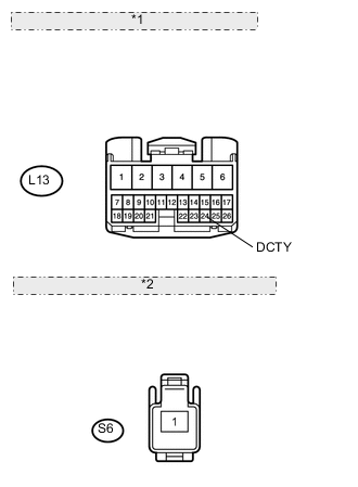
*1 Front view of wire harness connector: (to Main Body ECU) *2 Front view of wire harness connector: (to Front Door Courtesy Light Switch LH)
-
Disconnect the L13 ECU connector.
-
Disconnect the S6 switch connector.
-
Measure the resistance according to the value(s) in the table below.
Standard resistance Tester Connection Condition Specified Condition L13-24 (DCTY) - S6-1 Always Below 1 Ω L13-24 (DCTY) - Body ground Always 10 kΩ or higher
OK
REPLACE MAIN BODY ECU
NG
REPAIR OR REPLACE HARNESS OR CONNECTOR
-
-
CHECK HARNESS AND CONNECTOR (FRONT DOOR COURTESY LIGHT RH - FRONT MULTIPLEX NETWORK DOOR ECU RH)

*1 Front view of wire harness connector: (to Front Multiplex Network Door ECU RH) *2 CTYB *3 CYL *4 Front view of wire harness connector: (to Front Door Courtesy Light RH)
-
Disconnect the P4 ECU connector.
-
Disconnect the P5 light connector.
-
Measure the resistance according to the value(s) in the table below.
Standard resistance Tester Connection Condition Specified Condition P5-1 - P4-6 (CTYB) Always Below 1 Ω P5-2 - P4-7 (CYL) Always Below 1 Ω P5-1 - Body ground Always 10 kΩ or higher P5-2 - Body ground Always 10 kΩ or higher
NG
REPAIR OR REPLACE HARNESS OR CONNECTOR
OK
-
-
CHECK FRONT COURTESY LIGHT RH (OPERATION)
-
Temporarily replace the front door courtesy light RH with a new or normally functioning one Click here.
-
Check the front door courtesy light RH operation.
OK Front door courtesy light RH operation is normal.
OK
END (REPLACE FRONT DOOR COURTESY LIGHT RH) Click here
NG
REPLACE FRONT MULTIPLEX NETWORK DOOR ECU RH Click here
-
-
INSPECT FRONT DOOR COURTESY LIGHT SWITCH RH

*1 Component without harness connected: (Front Door Courtesy Light Switch RH)
-
Remove the front door courtesy light switch RH Click here.
-
Measure the resistance according to the value(s) in the table below.
Standard resistance Tester Connection Switch Condition Specified Condition 1 - Body ground Not pushed Below 1 Ω 1 - Body ground Pushed 10 kΩ or higher
NG
REPLACE FRONT DOOR COURTESY LIGHT SWITCH RH Click here
OK
-
-
CHECK HARNESS AND CONNECTOR (MAIN BODY ECU - FRONT DOOR COURTESY LIGHT SWITCH RH)
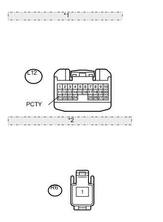
*1 Front view of wire harness connector: (to Main Body ECU) *2 Front view of wire harness connector: (to Front Door Courtesy Light Switch RH)
-
Disconnect the L12 ECU connector.
-
Disconnect the R6 switch connector.
-
Measure the resistance according to the value(s) in the table below.
Standard resistance Tester Connection Condition Specified Condition L12-21 (PCTY) - R6-1 Always Below 1 Ω L12-21 (PCTY) - Body ground Always 10 kΩ or higher
OK
REPLACE MAIN BODY ECU
NG
REPAIR OR REPLACE HARNESS OR CONNECTOR
-
-
CHECK HARNESS AND CONNECTOR (REAR DOOR COURTESY LIGHT LH - REAR MULTIPLEX NETWORK DOOR ECU LH)
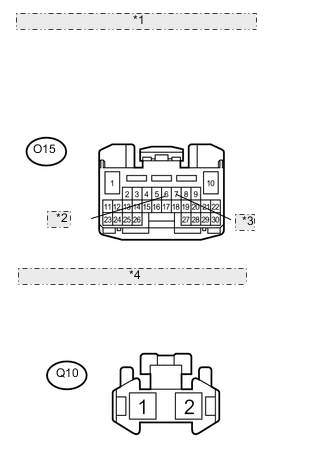
*1 Front view of wire harness connector: (to Rear Multiplex Network Door ECU LH) *2 CTYB *3 CYL *4 Front view of wire harness connector: (to Rear Door Courtesy Light LH)
-
Disconnect the O15 ECU connector.
-
Disconnect the Q10 light connector.
-
Measure the resistance according to the value(s) in the table below.
Standard resistance Tester Connection Condition Specified Condition Q10-1 - O15-6 (CTYB) Always Below 1 Ω Q10-2 - O15-7 (CYL) Always Below 1 Ω Q10-1 - Body ground Always 10 kΩ or higher Q10-2 - Body ground Always 10 kΩ or higher
NG
REPAIR OR REPLACE HARNESS OR CONNECTOR
OK
-
-
CHECK REAR COURTESY LIGHT LH (OPERATION)
-
Temporarily replace the rear door courtesy light LH with a new or normally functioning one Click here.
-
Check the rear door courtesy light LH operation.
OK Rear door courtesy light LH operation is normal.
OK
END (REPLACE REAR COURTESY LIGHT LH) Click here
NG
REPLACE REAR MULTIPLEX NETWORK DOOR ECU LH Click here
-
-
INSPECT REAR DOOR COURTESY LIGHT SWITCH LH
*1 Component without harness connected: (Rear Door Courtesy Light Switch LH)
-
Remove the rear door courtesy light switch LH Click here.
-
Measure the resistance according to the value(s) in the table below.
Standard resistance Tester Connection Switch Condition Specified Condition 1 - Body ground Not pushed Below 1 Ω 1 - Body ground Pushed 10 kΩ or higher
NG
REPLACE REAR DOOR COURTESY LIGHT SWITCH LH Click here
OK
-
-
CHECK HARNESS AND CONNECTOR (MAIN BODY ECU - REAR DOOR COURTESY LIGHT SWITCH LH)
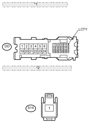
*1 Front view of wire harness connector: (to Main Body ECU) *2 Front view of wire harness connector: (to Rear Door Courtesy Light Switch LH)
-
Disconnect the DD ECU connector.
-
Disconnect the S14 switch connector.
-
Measure the resistance according to the value(s) in the table below.
Standard resistance Tester Connection Condition Specified Condition DD-12 (LCTY) - S14-1 Always Below 1 Ω DD-12 (LCTY)- Body ground Always 10 kΩ or higher
OK
REPLACE MAIN BODY ECU
NG
REPAIR OR REPLACE HARNESS OR CONNECTOR
-
-
CHECK HARNESS AND CONNECTOR (REAR DOOR COURTESY LIGHT RH - REAR MULTIPLEX NETWORK DOOR ECU RH)
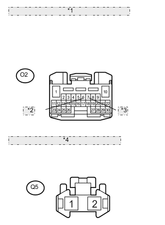
*1 Front view of wire harness connector: (to Rear Multiplex Network Door ECU RH) *2 CTYB *3 CYL *4 Front view of wire harness connector: (to Rear Door Courtesy Light RH)
-
Disconnect the O2 ECU connector.
-
Disconnect the Q5 light connector.
-
Measure the resistance according to the value(s) in the table below.
Standard resistance Tester Connection Condition Specified Condition Q5-1 - O2-6 (CTYB) Always Below 1 Ω Q5-2 - O2-7 (CYL) Always Below 1 Ω Q5-1 - Body ground Always 10 kΩ or higher Q5-2 - Body ground Always 10 kΩ or higher
NG
REPAIR OR REPLACE HARNESS OR CONNECTOR
OK
-
-
CHECK REAR COURTESY LIGHT RH (OPERATION)
-
Temporarily replace the rear door courtesy light RH with a new or normally functioning one Click here.
-
Check the rear door courtesy light RH operation.
OK Rear door courtesy light RH operation is normal.
OK
END (REPLACE REAR DOOR COURTESY LIGHT RH) Click here
NG
REPLACE REAR MULTIPLEX NETWORK DOOR ECU RH Click here
-
-
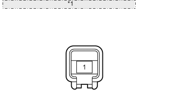
INSPECT REAR DOOR COURTESY LIGHT SWITCH RH

*1 Component without harness connected: (Rear Door Courtesy Light Switch RH)
-
Remove the rear door courtesy light switch RH Click here.
-
Measure the resistance according to the value(s) in the table below.
Standard resistance Tester Connection Switch Condition Specified Condition 1 - Body ground Not pushed Below 1 Ω 1 - Body ground Pushed 10 kΩ or higher
NG
REPLACE REAR DOOR COURTESY LIGHT SWITCH RH Click here
OK
-
-
CHECK HARNESS AND CONNECTOR (MAIN BODY ECU - REAR DOOR COURTESY LIGHT SWITCH RH)
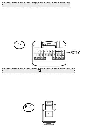
*1 Front view of wire harness connector: (to Main Body ECU) *2 Front view of wire harness connector: (to Rear Door Courtesy Light Switch RH)
-
Disconnect the L12 ECU connector.
-
Disconnect the R12 switch connector.
-
Measure the resistance according to the value(s) in the table below.
Standard resistance Tester Connection Condition Specified Condition L12-7 (RCTY) - R12-1 Always Below 1 Ω L12-7 (RCTY) - Body ground Always 10 kΩ or higher
OK
REPLACE MAIN BODY ECU
NG
REPAIR OR REPLACE HARNESS OR CONNECTOR
-