LIGHTING SYSTEM, Diagnostic DTC:B2402
| DTC Code | DTC Name |
|---|---|
| B2402 | Transistor Relay Overload Malfunction |
DESCRIPTION
The electric current flowing in the transistor inside the rear junction block is examined by the rear junction block ECU.
When excessive current is detected, DTC B2402 is output.
Turning off the power switch clears the DTC.
| DTC Code | DTC Detection Condition | Trouble Area |
|---|---|---|
| B2402 | Transistor relay overload malfunction |
|
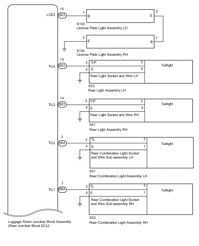
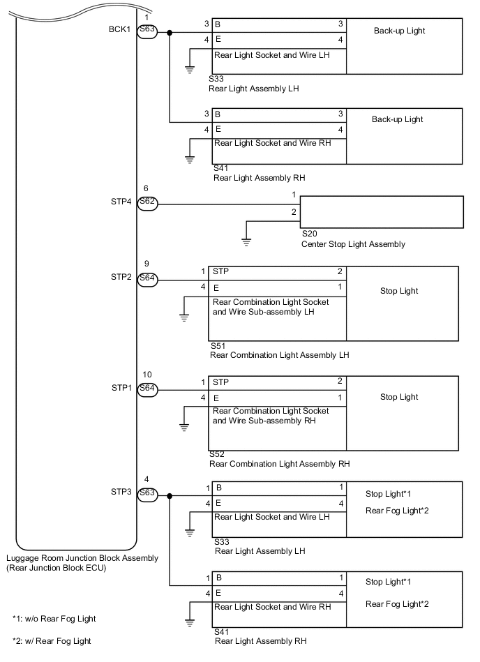
WIRING DIAGRAM
PROCEDURE
-
CHECK VEHICLE TYPE
-
Check the vehicle type.
Result Result Proceed to w/ Rear Fog Light A w/o Rear Fog Light B
B 
READ VALUE USING GTS (TAILLIGHT, STOP LIGHT, CENTER STOP LIGHT AND BACK-UP LIGHT) Click here
A 
-
-
READ VALUE USING GTS (REAR FOG LIGHT)
-
Using the GTS, read the Data List Click here.
Body No. 4 Tester Display Measurement Item/Range Normal Condition Diagnostic Note Rear Fog Light Tr. Rear fog light illumination condition display/OK or Break OK: Rear fog light circuit is normal
Break: Rear fog light circuit is malfunctioning
- Result Result Proceed to Item (Rear Fog Light Tr.) displays "OK" on the GTS A Item (Rear Fog Light Tr.) displays "Break" is on the GTS B
B
READ VALUE USING GTS (REAR FOG LIGHT) Click here
A
-
-
READ VALUE USING GTS (TAILLIGHT, STOP LIGHT, CENTER STOP LIGHT AND BACK-UP LIGHT)
-
Using the GTS, read the Data List Click here.
Body No. 4 Tester Display Measurement Item/Range Normal Condition Diagnostic Note Tail Light Tr States of taillight/OK or Break OK: Taillight circuit is normal
Break: Taillight circuit is malfunctioning
Confirm that headlight dimmer switch is ON (TAIL or HEAD position) Stop Light Tr States of stop light/OK or Break OK: Stop light circuit is normal
Break: Stop light circuit is malfunctioning
Confirm that brake pedal is pressed High Mount Stop Light Tr States of high mount stop light/OK or Break OK: High mount stop light circuit is normal
Break: High mount stop light circuit is malfunctioning
Confirm that brake pedal is pressed Backup Light Tr States of back-up light/OK or Break OK: Back-up light circuit is normal
Break: Back-up light circuit is malfunctioning
Confirm that shift lever in R Result Result Proceed to Item (Tail Light Tr.) displays "Break" on the GTS A Item (Stop Light Tr.) displays "Break" is on the GTS B Item (High Mount Stop Tr.) displays "Break" on the GTS C Item (Back-up Light Tr.) displays "Break" on the GTS D All items display "OK" on the GTS E
B
READ VALUE USING GTS (STOP LIGHT) Click here
C
READ VALUE USING GTS (CENTER STOP LIGHT) Click here
D
READ VALUE USING GTS (BACK-UP LIGHT) Click here
E
CHECK HARNESS AND CONNECTOR (REAR JUNCTION BLOCK ECU - LICENSE PLATE LIGHT LH) Click here
A
-
-
READ VALUE USING GTS (TAILLIGHT AND LICENSE PLATE LIGHT)
-
Disconnect the connectors in the following order: Rear combination light (LH, RH), rear light (LH, RH), license plate light.
-
Operate the power switch as follows each time a connector is disconnected: on (IG) → off →on (IG).
-
Using the GTS, read the Data List Click here.
Body No. 4 Tester Display Measurement Item/Range Normal Condition Diagnostic Note Tail Light Tr States of taillight/OK or Break OK: Taillight circuit is normal
Break: Taillight circuit is malfunctioning
Confirm that headlight dimmer switch is ON (TAIL or HEAD position) Result Disconnected Light Result Proceed to
-
Rear combination light
-
Rear light
-
License plate light
Displayed "Break" on the GTS A Rear combination light Displayed "OK" is on the GTS B Rear light Displayed "OK" is on the GTS C License plate light LH and RH Displayed "OK" is on the GTS D -
B
CHECK REAR COMBINATION LIGHT SOCKET AND WIRE SUB-ASSEMBLY Click here
C
CHECK REAR LIGHT SOCKET AND WIRE Click here
D
INSPECT LICENSE PLATE LIGHT ASSEMBLY LH Click here
A
-
-
READ VALUE USING GTS (TAILLIGHT)
-
Disconnect the connectors in the following order: rear junction block ECU connector S63, S64.
-
Operate the power switch as follows each time a connector is disconnected: on (IG) → off →on (IG).
-
Using the GTS, read the Data List Click here.
Body No. 4 Tester Display Measurement Item/Range Normal Condition Diagnostic Note Tail Light Tr States of taillight/OK or Break OK: Taillight circuit is normal
Break: Taillight circuit is malfunctioning
Confirm that headlight dimmer switch is ON (TAIL or HEAD position) Result Result Proceed to "Break" display does not change A Changes to "Normal" display B
A 
REPLACE LUGGAGE ROOM JUNCTION BLOCK (REAR JUNCTION BLOCK ECU)
B
REPAIR OR REPLACE HARNESS OR CONNECTOR
-
-
INSPECT LICENSE PLATE LIGHT ASSEMBLY LH
-
Remove the license plate light LH Click here.
-
Inspect the license plate light LH Click here.
OK
REPLACE LICENSE PLATE LIGHT ASSEMBLY RH Click here
NG
REPLACE LICENSE PLATE LIGHT ASSEMBLY LH Click here
-
-
READ VALUE USING GTS (REAR FOG LIGHT)
-
Disconnect the connectors in the following order: rear light (LH, RH).
-
Operate the power switch as follows each time a connector is disconnected: on (IG) → off →on (IG).
-
Using the GTS, read the Data List Click here.
Body No. 4 Tester Display Measurement Item/Range Normal Condition Diagnostic Note Rear Fog Light Tr. Rear fog light illumination condition display/OK or Break OK: Rear fog light circuit is normal
Break: Rear fog light circuit is malfunctioning
- Result Result Proceed to "Break" display does not change A Changes to "Normal" display B
B
CHECK REAR LIGHT SOCKET AND WIRE Click here
A
-
-
READ VALUE USING GTS (REAR FOG LIGHT)
-
Disconnect the connectors in the following order: rear junction block ECU connector S63.
-
Operate the power switch as follows each time a connector is disconnected: on (IG) → off →on (IG).
-
Using the GTS, read the Data List Click here.
Body No. 4 Tester Display Measurement Item/Range Normal Condition Diagnostic Note Rear Fog Light Tr. Rear fog light illumination condition display/OK or Break OK: Rear fog light circuit is normal
Break: Rear fog light circuit is malfunctioning
- Result Result Proceed to "Break" display does not change A Changes to "Normal" display B
A
REPLACE LUGGAGE ROOM JUNCTION BLOCK (REAR JUNCTION BLOCK ECU)
B
REPAIR OR REPLACE HARNESS OR CONNECTOR
-
-
READ VALUE USING GTS (STOP LIGHT)
-
Disconnect the connectors in the following order: rear combination light (LH, RH), rear light (LH, RH).
-
Operate the power switch as follows each time a connector is disconnected: on (IG) → off →on (IG).
-
Using the GTS, read the Data List Click here.
Body No. 4 Tester Display Measurement Item/Range Normal Condition Diagnostic Note Stop Light Tr States of stop light/OK or Break OK: Stop light circuit is normal
Break: Stop light circuit is malfunctioning
Confirm that brake pedal is pressed Result Disconnected Light Result Proceed to
-
Rear combination light
-
Rear light
"Break" display does not change A Rear combination light Changes to "Normal" display B Rear light Changes to "Normal" display C Tech Tips
Disconnect the RH connector, then the LH connector. If the display changes to "Normal", it can be determined that the disconnected light is malfunctioning.
-
B
CHECK REAR COMBINATION LIGHT SOCKET AND WIRE SUB-ASSEMBLY Click here
C
CHECK REAR LIGHT SOCKET AND WIRE Click here
A
-
-
READ VALUE USING GTS (STOP LIGHT)
-
Disconnect the connectors in the following order: rear junction block ECU connector S63, S64.
-
Operate the power switch as follows each time a connector is disconnected: on (IG) → off →on (IG).
-
Using the GTS, read the Data List Click here.
Body No. 4 Tester Display Measurement Item/Range Normal Condition Diagnostic Note Stop Light Tr States of stop light/OK or Break OK: Stop light circuit is normal
Break: Stop light circuit is malfunctioning
Confirm that brake pedal is pressed Result Result Proceed to "Break" display does not change A Changes to "Normal" display B
A
REPLACE LUGGAGE ROOM JUNCTION BLOCK (REAR JUNCTION BLOCK ECU)
B
REPAIR OR REPLACE HARNESS OR CONNECTOR
-
-
READ VALUE USING GTS (CENTER STOP LIGHT)
-
Disconnect the connectors in the following order: Center stop light.
-
Operate the power switch as follows each time a connector is disconnected: on (IG) → off →on (IG).
-
Using the GTS, read the Data List Click here.
Body No. 4 Tester Display Measurement Item/Range Normal Condition Diagnostic Note High Mount Stop Light Tr States of high mount stop light/OK or Break OK: High mount stop light circuit is normal
Break: High mount stop light circuit is malfunctioning
Confirm that brake pedal is pressed Result Result Proceed to "Break" display does not change A Changes to "Normal" display B
B
REPLACE CENTER STOP LIGHT ASSEMBLY Click here
A
-
-
READ VALUE USING GTS (CENTER STOP LIGHT)
-
Disconnect the connectors in the following order: rear junction block ECU connector S62.
-
Operate the power switch as follows each time a connector is disconnected: on (IG) → off →on (IG).
-
Using the GTS, read the Data List Click here.
Body No. 4 Tester Display Measurement Item/Range Normal Condition Diagnostic Note High Mount Stop Light Tr States of high mount stop light/OK or Break OK: High mount stop light circuit is normal
Break: High mount stop light circuit is malfunctioning
Confirm that brake pedal is pressed Result Result Proceed to "Break" display does not change A Changes to "Normal" display B
A
REPLACE LUGGAGE ROOM JUNCTION BLOCK (REAR JUNCTION BLOCK ECU)
B
REPAIR OR REPLACE HARNESS OR CONNECTOR
-
-
READ VALUE USING GTS (BACK-UP LIGHT)
-
Disconnect the connectors in the following order: rear light (LH, RH).
-
Operate the power switch as follows each time a connector is disconnected: on (IG) → off →on (IG).
-
Using the GTS, read the Data List Click here.
Body No. 4 Tester Display Measurement Item/Range Normal Condition Diagnostic Note Backup Light Tr States of back-up light/OK or Break OK: Back-up light circuit is normal
Break: Back-up light circuit is malfunctioning
Confirm that shift lever in R Result Result Proceed to "Break" display does not change A Changes to "Normal" display B
B
CHECK REAR LIGHT SOCKET AND WIRE Click here
A
-
-
READ VALUE USING GTS (BACK-UP LIGHT)
-
Disconnect the connectors in the following order: rear junction block ECU connector S63.
-
Operate the power switch as follows each time a connector is disconnected: on (IG) → off →on (IG).
-
Using the GTS, read the Data List Click here.
Body No. 4 Tester Display Measurement Item/Range Normal Condition Diagnostic Note Backup Light Tr States of back-up light/OK or Break OK: Back-up light circuit is normal
Break: Back-up light circuit is malfunctioning
Confirm that shift lever in R Result Result Proceed to "Break" display does not change A Changes to "Normal" display B
A
REPLACE LUGGAGE ROOM JUNCTION BLOCK (REAR JUNCTION BLOCK ECU)
B
REPAIR OR REPLACE HARNESS OR CONNECTOR
-
-
CHECK HARNESS AND CONNECTOR (REAR JUNCTION BLOCK ECU - LICENSE PLATE LIGHT LH)
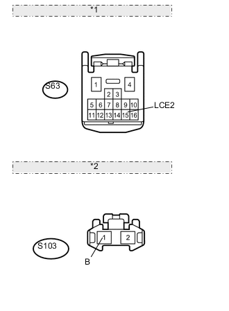
*1 Front view of wire harness connector: (to Rear Junction Block ECU) *2 Front view of wire harness connector: (to License Plate Light LH)
-
Disconnect the S63 rear junction block ECU connector.
-
Disconnect the S103 license plate light LH connector.
-
Measure the resistance according to the value(s) in the table below.
Standard Resistance Tester Connection Condition Specified Condition S63-15 (LCE2) - S103-1 (B) Always Below 1 Ω S63-15 (LCE2) - Body ground Always 10 kΩ or higher
NG
REPAIR OR REPLACE HARNESS OR CONNECTOR
OK
-
-
CHECK HARNESS AND CONNECTOR (LICENSE PLATE LIGHT RH - LICENSE PLATE LIGHT LH AND BODY GROUND)
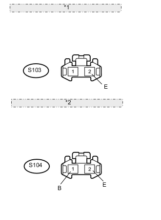
*1 Front view of wire harness connector: (to License Plate Light LH) *2 Front view of wire harness connector: (to License Plate Light RH)
-
Disconnect the S103 license plate light LH connector.
-
Disconnect the S104 license plate light RH connector.
-
Measure the resistance according to the value(s) in the table below.
Standard Resistance Tester Connection Condition Specified Condition S103-2 (E) - S104-1 (B) Always Below 1 Ω S104-2 (E) - Body ground Always Below 1 Ω S103-2 (E) - Body ground Always 10 kΩ or higher
NG
REPAIR OR REPLACE HARNESS OR CONNECTOR
OK
-
-
CHECK HARNESS AND CONNECTOR (REAR JUNCTION BLOCK ECU - REAR LIGHT AND BODY GROUND)
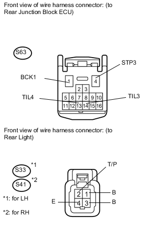
-
Disconnect the S63 rear junction block ECU connector.
-
Disconnect the S33*1 and S41*2 rear light connectors.
-
*1: for LH
-
*2: for RH
-
-
Measure the resistance according to the value(s) in the table below.
Standard Resistance for LH Tester Connection Condition Specified Condition S63-13 (TIL4) - S33-2 (T/P) Always Below 1 Ω S33-4 (E) - Body ground Always Below 1 Ω S63-13 (TIL4) - Body ground Always 10 kΩ or higher S63-1 (BCK1) - S33-3 (B) Always Below 1 Ω S63-1 (BCK1) - Body ground Always 10 kΩ or higher S63-4 (STP3) - S33-1 (B) Always Below 1 Ω S33-4 (E) - Body ground Always Below 1 Ω S63-4 (STP3) - Body ground Always 10 kΩ or higher for RH Tester Connection Condition Specified Condition S63-14 (TIL3) - S41-2 (T/P) Always Below 1 Ω S41-4 (E) - Body ground Always Below 1 Ω S63-14 (TIL3) - Body ground Always 10 kΩ or higher S63-1 (BCK1) - S41-3 (B) Always Below 1 Ω S63-1 (BCK1) - Body ground Always 10 kΩ or higher S63-4 (STP3) - S41-1 (B) Always Below 1 Ω S41-4 (E) - Body ground Always Below 1 Ω S63-4 (STP3) - Body ground Always 10 kΩ or higher
NG
REPAIR OR REPLACE HARNESS OR CONNECTOR
OK
-
-
CHECK HARNESS AND CONNECTOR (REAR JUNCTION BLOCK ECU - REAR COMBINATION LIGHT AND BODY GROUND)
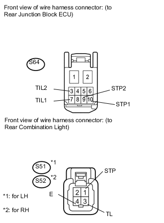
-
Disconnect the S64 rear junction block ECU connector.
-
Disconnect the S51*1 and S52*2 rear combination light connectors.
-
*1: for LH
-
*2: for RH
-
-
Measure the resistance according to the value(s) in the table below.
Standard Resistance for LH Tester Connection Condition Specified Condition S64-3 (TIL2) - S51-3 (TL) Always Below 1 Ω S64-3 (TIL2) - Body ground Always 10 kΩ or higher S64-9 (STP2) - S51-1 (STP) Always Below 1 Ω S51-4 (E) - Body ground Always Below 1 Ω S64-9 (STP2) - Body ground Always 10 kΩ or higher for RH Tester Connection Condition Specified Condition S64-7 (TIL1) - S52-3 (TL) Always Below 1 Ω S52-4 (E) - Body ground Always Below 1 Ω S64-7 (TIL1) - Body ground Always 10 kΩ or higher S64-10 (STP1) - S52-1 (STP) Always Below 1 Ω S64-10 (STP1) - Body ground Always 10 kΩ or higher
NG
REPAIR OR REPLACE HARNESS OR CONNECTOR
OK
-
-
CHECK HARNESS AND CONNECTOR (REAR JUNCTION BLOCK ECU - CENTER STOP LIGHT AND BODY GROUND)
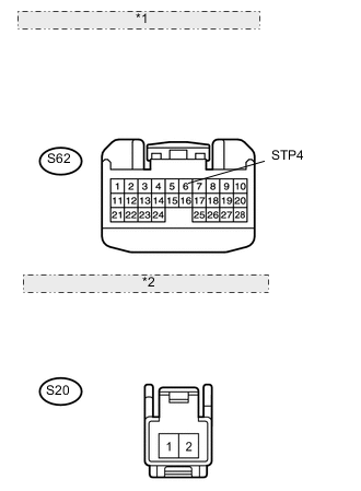
*1 Front view of wire harness connector: (to Rear Junction Block ECU) *2 Front view of wire harness connector: (to Center Stop Light)
-
Disconnect the S62 rear junction block ECU connector.
-
Disconnect the S20 center stop light connector.
-
Measure the resistance according to the value(s) in the table below.
Standard Resistance Tester Connection Condition Specified Condition S62-6 (STP4) - S20-1 Always Below 1 Ω S20-2 - Body ground Always Below 1 Ω S62-6 (STP4) - Body ground Always 10 kΩ or higher
OK
REPLACE LUGGAGE ROOM JUNCTION BLOCK (REAR JUNCTION BLOCK ECU)
NG
REPAIR OR REPLACE HARNESS OR CONNECTOR
-
-
CHECK REAR COMBINATION LIGHT SOCKET AND WIRE SUB-ASSEMBLY
-
Temporarily replace the rear combination light socket and wire with a new or normally functioning one Click here.
-
Check for DTC Click here.
OK DTC B2402 output does not occur
OK
END (REAR COMBINATION LIGHT SOCKET AND WIRE WAS DEFECTIVE)
NG
REPLACE REAR COMBINATION LIGHT ASSEMBLY Click here
-
-
CHECK REAR LIGHT SOCKET AND WIRE
-
Temporarily replace the rear light socket and wire with a new or normally functioning one Click here.
-
Check for DTC Click here.
OK DTC B2402 output does not occur
OK
END (REAR LIGHT SOCKET AND WIRE WAS DEFECTIVE)
NG
REPLACE REAR LIGHT ASSEMBLY Click here
-