THEFT DETERRENT SYSTEM, Diagnostic DTC:B2762
| DTC Code | DTC Name |
|---|---|
| B2762 | Intrusion Sensor Signal Circuit Malfunction |
DESCRIPTION
-
The intrusion sensor (theft warning ultrasonic sensor) conducts self-diagnosis immediately after power is supplied to the sensor (when the theft deterrent system is set).
If a malfunction is detected in the IOUT line, the certification ECU stores this DTC.
| DTC Code | DTC Detection Condition | Trouble Area |
|---|---|---|
| B2762 | After normal/trouble signal is output from intrusion sensor (theft warning ultrasonic sensor) as result of self-diagnosis, following malfunctions are detected:
|
|
WIRING DIAGRAM
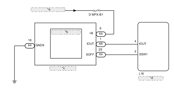
| *a | from Auxiliary Battery |
| *b | Intrusion Sensor (Theft Warning Ultrasonic Sensor) |
| *c | Map Light Assembly |
| *d | Certification ECU |
CAUTION / NOTICE / HINT
Note
-
If the certification ECU is replaced, refer to the Service Bulletin.
-
Inspect the fuses for circuits related to this system before performing the following inspection procedure.
PROCEDURE
-
CHECK HARNESS AND CONNECTOR (MAP LIGHT ASSEMBLY - BATTERY AND BODY GROUND)
-
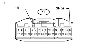
Text in Illustration *a Front view of wire harness connector
(to Map Light Assembly)
Disconnect the map light assembly connector.
-
Measure the voltage according to the value(s) in the table below.
Standard Voltage Tester Connection Condition Specified Condition X4-6 (+B) - Body ground Always 11 to 14 V -
Measure the resistance according to the value(s) in the table below.
Standard Resistance Tester Connection Condition Specified Condition X4-16 (GND9) - Body ground Always Below 1 Ω
NG 
REPAIR OR REPLACE HARNESS OR CONNECTOR
OK 
-
-
CHECK INTRUSION SENSOR (THEFT WARNING ULTRASONIC SENSOR) (IOUT)
-
Using an oscilloscope, check the waveform.
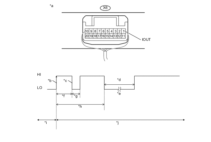
Text in Illustration *a Component with harness connected
(Map Light Assembly)
*b IOUT Initial Signal *c IOUT Initial Response *d Approximately 1.0 seconds *e Initial Diagnosis *f Approximately 1.0 to 1.6 seconds *g Approximately 0.05 seconds *h Approximately 5.5 seconds *i Disarmed State *j Arming Preparation State Measurement Condition Tester Connection Content Tester Connection X6-1 (IOUT) - Body ground Tool Setting 2 V/DIV., 100 ms./DIV. Condition Theft deterrent system is set (system changes from disarmed state to arming preparation state) Tech Tips
-
If the intrusion sensor (theft warning ultrasonic sensor) is normal, an initial response is output in response to the HI input from the certification ECU.
-
If the waveform output remains LO, there may be a problem with the certification ECU, as there is no input from the certification ECU.
OK The waveform displays properly (HI is 6.5 V or higher and LO is below 1 V). Result Result Proceed to NG (Waveform output remains LO) A NG (There is no initial response and the waveform output remains HI) B OK (There is an initial response) C -
B 
REPLACE MAP LIGHT ASSEMBLY Click here
C
USE SIMULATION METHOD TO CHECK Click here
A
-
-
CHECK HARNESS AND CONNECTOR (CERTIFICATION ECU - MAP LIGHT ASSEMBLY)
-
Disconnect the L16 certification ECU connector.
-
Disconnect the X6 map light assembly connector.
-
Measure the resistance according to the value(s) in the table below.
Standard Resistance Tester Connection Condition Specified Condition L16-4 (IOUT) - X6-1 (IOUT) Always Below 1 Ω L16-4 (IOUT) - Body ground Always 10 kΩ or higher
OK
REPLACE CERTIFICATION ECU
NG
REPAIR OR REPLACE HARNESS OR CONNECTOR
-
-
REPLACE MAP LIGHT ASSEMBLY
-
Temporarily replace the map light assembly with a new or normally functioning one Click here.
NEXT
-
-
CHECK FOR DTC
-
Clear the DTCs Click here.
-
Turn the power switch on (IG), then off.
-
Set the theft deterrent system to "ARMED STATE".
-
Check that the security indicator changes from illuminated to blinking.
-
Set the theft deterrent system to "DISARMED STATE".
-
Check for DTCs Click here.
OK DTC B2762 is not output.
OK
END (MAP LIGHT ASSEMBLY WAS DEFECTIVE)
NG
REPLACE INTRUSION SENSOR (THEFT WARNING ULTRASONIC SENSOR) Click here
-