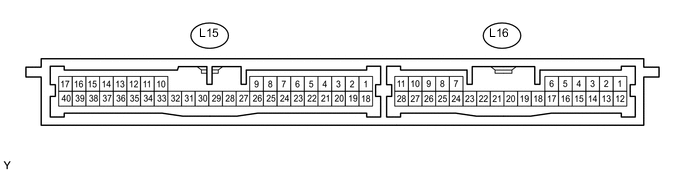
THEFT DETERRENT SYSTEM TERMINALS OF ECU
-
CHECK CERTIFICATION ECU
-
Disconnect the L15 and L16 ECU connectors.
-
Measure the resistance and voltage according to the value(s) in the table below.
Terminal No. (Symbols) Wiring Color Terminal Description Condition Specified Condition L15-1 (+B1) - Body ground L - Body ground +B power supply Always 11 to 14 V L15-18 (IG) - Body ground L - Body ground IG power supply Power switch ON (IG) 11 to 14 V L15-17 (E) - Body ground W-B - Body ground Ground Always Below 1 Ω
-
If the result is not as specified, there may be a malfunction on the wire harness side.
-
-
Reconnect the L15 and L16 ECU connectors.
-
Measure the voltage according to the value(s) in the table below.
Terminal No. (Symbols) Wiring Color Terminal Description Condition Specified Condition L15-2 (IND) - Body ground L - Body ground Security indicator signal Security indicator illuminates (illuminates only for 60 sec. in alarm sounding state (it is blinking when system is in armed state)) 3 to 6 V L16-7 (SSCL)*1 - Body ground BE - Body ground Theft warning siren signal Theft warning siren is sounding (theft warning system is in alarm sounding state) Pulse generation L16-4 (IOUT)*2 - Body ground W - Body ground Intrusion sensor signal input No moving object is detected 11 to 14 V Moving object is detected during arming preparation state or armed state Pulse generation L16-5 (SSW1)*2 - Body ground R - Body ground Intrusion sensor cancel switch signal Intrusion sensor cancel switch ON Below 1 V Intrusion sensor cancel switch OFF 11 to 14 V L16-21 (INCS)*3 - Body ground P - Body ground Tilt sensor signal input Vehicle tilt is not detected 11 to 14 V Vehicle tilt is detected during arming preparation state or armed state Pulse generation Tech Tips
*1: w/ Theft Warning Siren
*2: w/ Intrusion Sensor
*3: w/ Tilt Sensor
-
-
CHECK MAIN BODY ECU (DRIVER SIDE JUNCTION BLOCK)
-
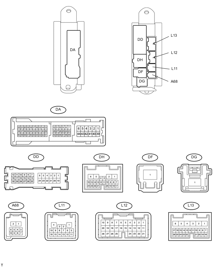
Disconnect the DA and DF ECU connectors.
-
Measure the resistance and voltage according to the value(s) in the table below.
Terminal No. (Symbols) Wiring Color Terminal Description Condition Specified Condition DA-40 (GND2) - Body ground W-B - Body ground Ground Always Below 1 Ω DF-1 (ALTB) - Body ground B - Body ground ECU power supply Always 11 to 14 V
-
-
CHECK FRONT DOOR ECU LH
-
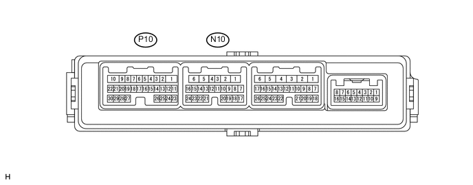
Disconnect the N10 ECU connector.
-
Measure the resistance and voltage according to the value(s) in the table below.
Terminal No. (Symbols) Wiring Color Terminal Description Condition Specified Condition N10-11 (CPUB) - Body ground B*1 - Body ground
R*2 - Body ground
ECU power supply Always 11 to 14 V N10-6 (BDR) - Body ground BE - Body ground ECU power supply Always 11 to 14 V N10-3 (SIG) - Body ground L*1 - Body ground
V*2 - Body ground
IG power supply Power switch ON (IG) 11 to 14 V N10-1 (GND) - Body ground W-B - Body ground Ground Always Below 1 Ω Tech Tips
*1: for LHD
*2: for RHD
-
If the result is not as specified, there may be a malfunction on the wire harness side.
-
-
Reconnect the N10 ECU connector.
-
Measure the voltage according to the value(s) in the table below.
Terminal No. (Symbols) Wiring Color Terminal Description Condition Specified Condition N10-23 (SID1) - Body ground L - Body ground Security indicator signal Security indicator illuminates (illuminates only for 60 seconds. in alarm sounding state (it is blinking when system is in armed state)) 3 to 6 V
-
-
CHECK FRONT DOOR ECU RH
-
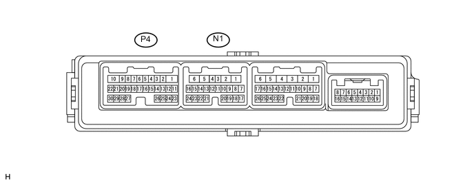
Disconnect the N1 ECU connector.
-
Measure the resistance and voltage according to the value(s) in the table below.
Terminal No. (Symbols) Wiring Color Terminal Description Condition Specified Condition N1-11 (CPUB) - Body ground R*1 - Body ground
B*2 - Body ground
ECU power supply Always 11 to 14 V N1-6 (BDR) - Body ground BE - Body ground ECU power supply Always 11 to 14 V N1-3 (SIG) - Body ground V*1 - Body ground
L*2 - Body ground
IG power supply Power switch ON (IG) 11 to 14 V N1-1 (GND) - Body ground W-B - Body ground Ground Always Below 1 Ω Tech Tips
*1: for LHD
*2: for RHD
-
If the result is not as specified, there may be a malfunction on the wire harness side.
-
-
Reconnect the N1 ECU connector.
-
Measure the voltage according to the value(s) in the table below.
Terminal No. (Symbols) Wiring Color Terminal Description Condition Specified Condition N1-23 (SID1) - Body ground L - Body ground Security indicator signal Security indicator illuminates (illuminates only for 60 seconds. in alarm sounding state (it is blinking when system is in armed state)) 3 to 6 V
-
-
CHECK FRONT CONTROLLER
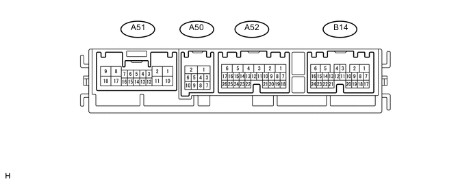
-
Disconnect the A50, A51, A52 and B14 front controller connectors.
-
Measure the resistance and voltage according to the value(s) in the table below.
Terminal No. (Symbols) Wiring Color Terminal Description Condition Specified Condition A52-5 (ALTB) - Body ground L - Body ground +B power supply Always 11 to 14 V A52-1 (BATB) - Body ground P - Body ground +B power supply Always 11 to 14 V A50-1 (FMB3) - Body ground LG - Body ground +B power supply Always 11 to 14 V A50-5 (FMIG) - Body ground Y - Body ground IG power supply Power switch ON (IG) 11 to 14 V A50-2 (E) - Body ground W-B - Body ground Ground Always Below 1 Ω
-
If the result is not as specified, there may be a malfunction on the wire harness side.
-
-
Reconnect the A50, A51, A52 and B14 front controller connectors.
-
Measure the voltage and resistance according to the value(s) in the table below.
Terminal No. (Symbols) Wiring Color Terminal Description Condition Specified Condition A52-4 (SH-) - Body ground W - Body ground Security horn signal Security horn is sounding (theft deterrent system is in alarm sounding state) Pulse generation B14-21 (HDCY) - Body ground G - Body ground Engine hood courtesy switch signal Engine hood closed 10 kΩ or higher Engine hood open Below 1 Ω
-