REAR EVAPORATOR TEMPERATURE SENSOR(w/o Rear Air Conditioning System) INSTALLATION
PROCEDURE
-
INSTALL NO. 2 COOLER THERMISTOR
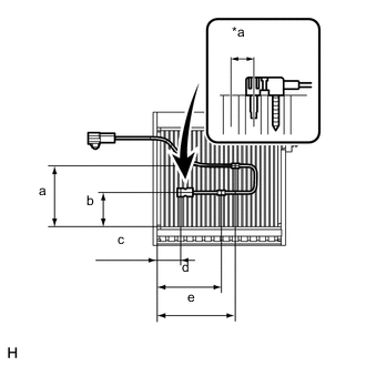
Text in Illustration *a 1 Fin Note
If reusing the evaporator, do not insert the sensor into a location where the No. 2 cooler thermistor was previously inserted.
-
Insert the No. 2 cooler thermistor to a location that is 1 fin to the right or left of its previous location.
Area Standard Dimension a 85 to 95 mm (3.35 to 3.74 in.) b 45 to 55 mm (1.78 to 2.16 in.) c 34.3 mm (1.35 in.) d 114.8 mm (4.52 in.) e 128.1 mm (5.04 in.)
-
-
INSTALL REAR EVAPORATOR SUB-ASSEMBLY
-
INSTALL NO. 2 WIRING AIR CONDITIONER HARNESS SUB-ASSEMBLY
-
INSTALL REAR BLOWER WITH FAN MOTOR SUB-ASSEMBLY
-
INSTALL AIR CONDITIONING TUBE ASSEMBLY
-
INSTALL REAR COOLING UNIT EXPANSION VALVE
-
INSTALL NO. 2 AIR CONDITIONING TUBE AND ACCESSORY ASSEMBLY
-
INSTALL NO. 2 REAR COOLING UNIT DAMPER SERVO SUB-ASSEMBLY
-
INSTALL DRAIN COOLER HOSE
-
INSTALL REAR COOLING UNIT ASSEMBLY