AIR CONDITIONING UNIT INSTALLATION
CAUTION / NOTICE / HINT
Tech Tips
-
Use the same procedure for RHD and LHD vehicles.
-
The procedure listed below is for LHD vehicles.
-
A bolt without a torque specification is shown in the standard bolt chart Click here.
PROCEDURE
-
INSTALL AIR CONDITIONER UNIT ASSEMBLY
-
Install the air conditioning unit with the nut.
- Torque:
- 9.8 N*m { 100 kgf*cm, 87 in.*lbf }
-
-
INSTALL INSTRUMENT PANEL REINFORCEMENT ASSEMBLY
-
Install the instrument panel reinforcement with the No. 1 instrument panel spacer.
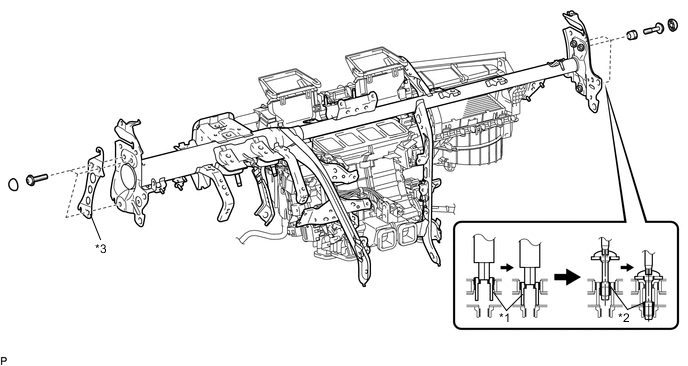
Text in Illustration *1 Collar *2 "TORX" Bolt *3 No. 1 Instrument Panel Spacer - - -
Passenger side:
Using a 12 mm hexagon wrench, tighten the 3 collars.
-
Using a T40 "TORX" socket, install the 6 "TORX" bolts.
- Torque:
- 20 N*m { 204 kgf*cm, 15 ft.*lbf }
-
Install the 6 instrument panel safety pad caps.
-
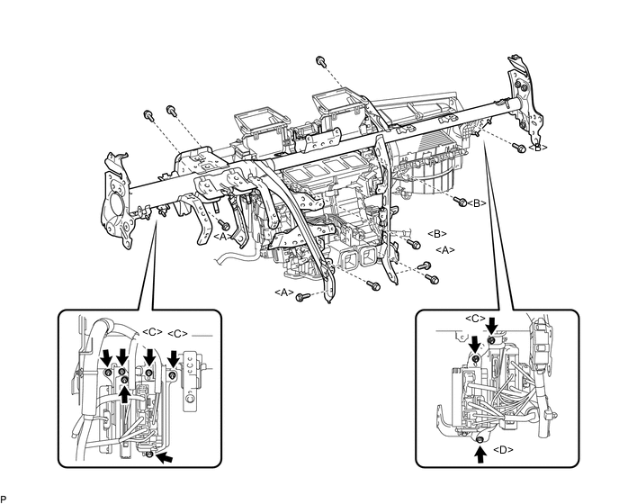
Install the 9 bolts and 2 screws.
- Torque:
- for Bolt A
- 20 N*m { 204 kgf*cm, 15 ft.*lbf }
- for Bolt B
- 9.8 N*m { 100 kgf*cm, 87 in.*lbf }
-
Connect the ground wires and install the junction block with the bolts and nuts.
- Torque:
- for Nut C
- 8.0 N*m { 82 kgf*cm, 71 in.*lbf }
- for Bolt D
- 13 N*m { 127 kgf*cm, 9 ft.*lbf }
-
Attach the clamps and connectors and install the wire harness.
-
-
INSTALL WINDSHIELD WIPER MOTOR ASSEMBLY
-
CONNECT COOLER UNIT DRAIN HOSE
-
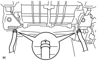
Connect the 2 cooler unit drain hoses as shown in the illustration.
-
-
INSTALL STEERING COLUMN ASSEMBLY
-
INSTALL NO. 1 AIR DUCT SUB-ASSEMBLY
-
Attach the 2 claws to install the No. 1 air duct sub-assembly.
-
Install the bolt.
- Torque:
- 9.8 N*m { 100 kgf*cm, 87 in.*lbf }
-
-
INSTALL NO. 2 AIR DUCT SUB-ASSEMBLY
-
Attach the 2 claws to install the No. 2 air duct sub-assembly.
-
Install the screw.
-
-
INSTALL INSTRUMENT PANEL SAFETY PAD SUB-ASSEMBLY
-
CONNECT HEATER WATER OUTLET HOSE
-
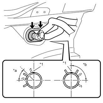
Text in Illustration *1 Paint Mark *a 30° to 60° *b 75° to 105° Connect the heater water outlet hose and attach the clip.
Tech Tips
Perform the installation with the hose clip and mark at the correct angle.
-
-
CONNECT HEATER WATER INLET HOSE
Tech Tips
Use the same procedure described for the water outlet hose.
-
CONNECT COOLER REFRIGERANT LIQUID PIPE A
-
Remove the attached vinyl tape from the pipe.
-
Sufficiently apply compressor oil to a new O-ring and the fitting surface of the cooler refrigerant liquid pipe A.
Compressor oil ND-OIL 11 or equivalent -
Install the O-ring to the cooler refrigerant liquid pipe A.
-
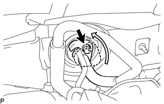
Connect the cooler refrigerant liquid pipe A.
-
Turn the hook connector in the direction indicated by the arrow in the illustration.
-
Install the bolt.
- Torque:
- 9.8 N*m { 100 kgf*cm, 7 ft.*lbf }
-
-
CONNECT SUCTION TUBE SUB-ASSEMBLY B
-
Remove the attached vinyl tape from the tube.
-
Sufficiently apply compressor oil to a new O-ring and the fitting surface of the suction tube sub-assembly B.
Compressor oil ND-OIL 11 or equivalent -
Install the O-ring to the suction tube sub-assembly B.
-
Connect the suction tube sub-assembly B.
-
Turn the hook connector in the direction indicated by the arrow in the illustration.
-
Install the bolt.
- Torque:
- 9.8 N*m { 100 kgf*cm, 7 ft.*lbf }
-
-
CONNECT CABLE TO NEGATIVE AUXILIARY BATTERY TERMINAL
Note
When disconnecting the cable, some systems need to be initialized after the cable is reconnected Click here.
-
ADD ENGINE COOLANT
-
ADD COMPRESSOR OIL
-
CHARGE REFRIGERANT
-
WARM UP ENGINE
-
CHECK FOR ENGINE COOLANT LEAKS
-
CHECK FOR LEAKAGE OF REFRIGERANT
-
CHECK SRS WARNING LIGHT
-
INSTALL BATTERY SERVICE HOLE COVER LH
-
INSTALL DECK TRIM SIDE BOARD LH (w/o Spare Tire)
-
INSTALL DECK BOARD ASSEMBLY (w/o Spare Tire)
-
INSTALL LUGGAGE COMPARTMENT MAT SUB-ASSEMBLY (w/ Spare Tire)