AIR CONDITIONING UNIT REASSEMBLY
CAUTION / NOTICE / HINT
Tech Tips
A bolt without a torque specification is shown in the standard bolt chart Click here.
PROCEDURE
-
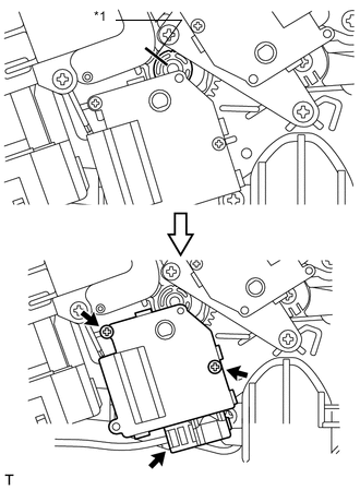
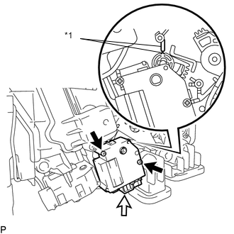
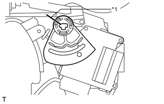
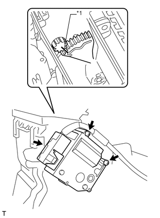
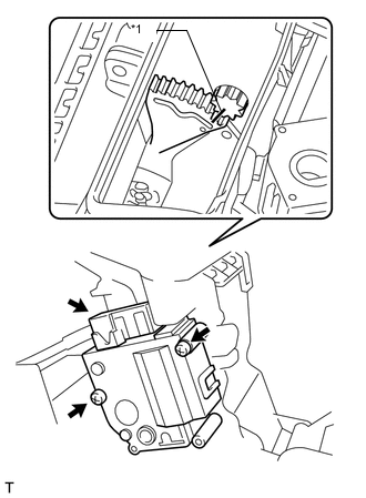
INSTALL MAX HOT BYPASS SERVO MOTOR (Cool) (for LHD)
-
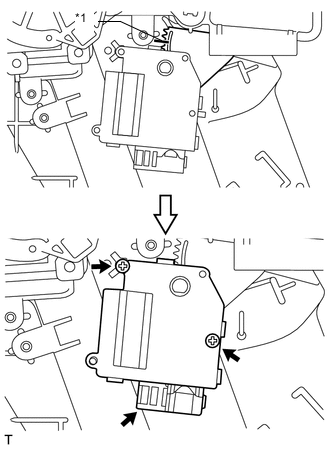
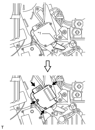
Install the max hot bypass servo motor (cool) with the 3 screws.
-
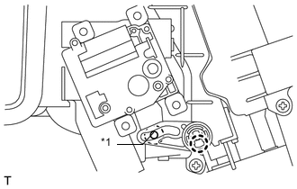
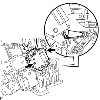
Text in Illustration *1 Pin Attach the claw to install the lever, as shown in the illustration.
-
-
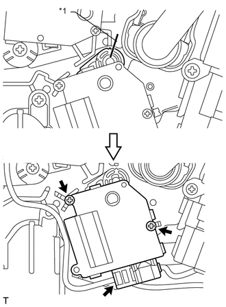
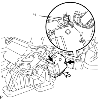
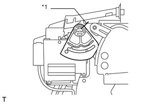
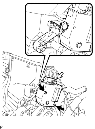
INSTALL MAX HOT BYPASS SERVO MOTOR (Cool) (for RHD)
-
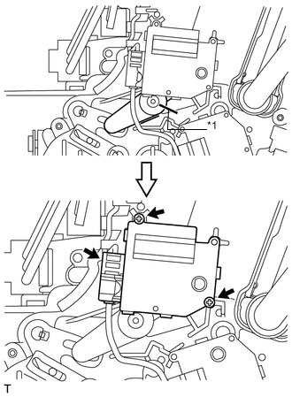
Install the max hot bypass servo motor (cool) with the 3 screws.
-
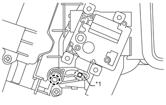
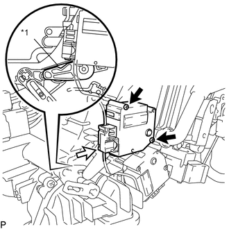
Text in Illustration *1 Pin Attach the claw to install the lever, as shown in the illustration.
-
-
INSTALL COOLER EXPANSION VALVE
-
Sufficiently apply compressor oil to 4 new O-rings, the fitting surface of the evaporator sub-assembly and the air conditioner tube.
Compressor oil ND-OIL8 or equivalent -
Install the 2 O-rings to the evaporator sub-assembly.
-
Install the 2 O-rings to the air conditioner tube assembly.
-
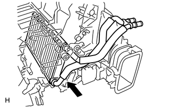
Install the cooler expansion valve and air conditioner tube assembly to the evaporator sub-assembly.
-
Using a 4 mm hexagon wrench, install the 2 hexagon bolts.
- Torque:
- 3.5 N*m { 35 kgf*cm, 30 in.*lbf }
-
-
INSTALL NO. 1 COOLER THERMISTOR
-
INSTALL NO. 1 COOLER EVAPORATOR SUB-ASSEMBLY
-
Install the No. 1 evaporator sub-assembly to the front cooling unit case (front side).
-
Attach the 3 claws to install the front cooling unit case (back side) to the front cooling unit case (front case).
-
Install the 6 screws.
-
Attach the hook to install the bracket to the air conditioner tube assembly, and install the holding spring.
-
Install a new packing to the bracket.
-
Tightly wrap a new No. 2 cooling unit packing to prevent exposure of the expansion valve and air conditioner tube assembly, and then wrap a new No. 3 cooling unit packing over the No. 2 cooling unit packing.
-
-
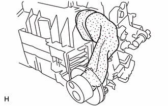
INSTALL HEATER RADIATOR UNIT SUB-ASSEMBLY
-
Install the heater radiator unit sub-assembly as shown in the illustration.
-
Install the clamp with the screw.
-
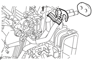
Install a new packing to the clamp.
-
-
INSTALL AIR CONDITIONING HARNESS ASSEMBLY
-
INSTALL QUICK HEATER ASSEMBLY
-
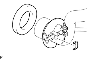
INSTALL AIR OUTLET SERVO MOTOR LH (Foot/Def)
-
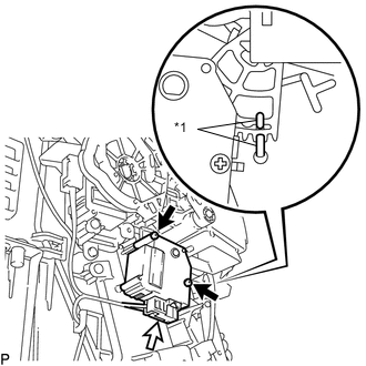
Install the front air outlet servo motor LH (foot/def) with the 3 screws.
-
Connect the connector.
-
Text in Illustration *1 Pin Attach the claw to install the main plate as shown in the illustration.
-
-
INSTALL AIR OUTLET SERVO MOTOR RH (Foot/Def)
-
Install the air outlet servo motor RH (foot/def) with the 3 screws.
-
Connect the connector.
-
Text in Illustration *1 Pin Attach the claw to install the main plate.
-
-
INSTALL MAX HOT BYPASS SERVO MOTOR (Hot)
Text in Illustration *1 Alignment Marks
-
When reusing the max hot air bypass servo motor (hot):
Align the moving parts and air conditioning unit as shown in the illustration and install the max hot air bypass servo motor (hot) with the 2 screws.
-
Text in Illustration *1 Protruding Part When using the new max hot air bypass servo motor (hot):
Align the protruding parts on the case and cover, and then install the max hot air bypass servo motor (hot) with the 2 screws.
-
Connect the connector.
-
-
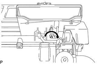
INSTALL AIR MIX SERVO MOTOR LH (Hot)
-
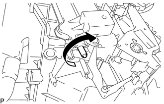
Make sure that the rod does not rotate further by trying to rotate it clockwise.
-
Install the air mix servo motor LH (Hot) with the 2 screws.
-
Connect the connector.
-
-
INSTALL AIR MIX SERVO MOTOR RH (Hot)
-
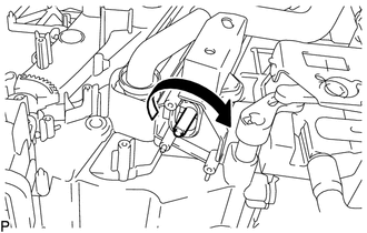
Make sure that the rod does not rotate further by trying to rotate it clockwise.
-
Install the air mix servo motor RH (Hot) with the 2 screws.
-
Connect the connector.
-
-
INSTALL AIR MIX SERVO MOTOR LH (Front A/C Rear Air Flow)
Text in Illustration *1 Alignment Marks
-
When reusing the air mix servo motor LH (front A/C rear air flow):
Align the moving parts and air conditioning unit as shown in the illustration and install the air mix servo motor LH (front A/C rear air flow) with the 2 screws.
-
Text in Illustration *1 Protruding Part When using the new air mix servo motor LH (front A/C rear air flow):
Align the protruding parts on the case and cover, and then install the air mix servo motor LH (front A/C rear air flow) with the 2 screws.
-
Connect the connector.
-
-
INSTALL AIR MIX SERVO MOTOR RH (Front A/C Rear Air Flow)
Text in Illustration *1 Alignment Marks
-
When reusing the air mix servo motor RH (front A/C rear air flow):
Align the moving parts and air conditioning unit as shown in the illustration and install the air mix servo motor RH (front A/C rear air flow) with the 2 screws.
-
Text in Illustration *1 Protruding Part When using the new air mix servo motor RH (front A/C rear air flow):
Align the protruding parts on the case and cover, and then install the air mix servo motor RH (front A/C rear air flow) with the 2 screws.
-
Connect the connector.
-
-
INSTALL AIR OUTLET SERVO MOTOR LH (Front A/C Rear Air Flow)
Text in Illustration *1 Alignment Marks
-
When reusing the air outlet servo motor LH (front A/C rear air flow):
Align the moving parts and air conditioning unit as shown in the illustration and install the air outlet servo motor LH (front A/C rear air flow) with the 2 screws.
-
Text in Illustration *1 Matchmark When using the new air outlet servo motor LH (front A/C rear air flow):
Align the lever with the matchmark as shown in the illustration.
-
Install the air outlet servo motor LH (front A/C rear air flow) with the 2 screws.
-
Connect the connector.
-
-
INSTALL AIR OUTLET SERVO MOTOR RH (Front A/C Rear Air Flow)
Text in Illustration *1 Alignment Marks
-
When reusing the air outlet servo motor RH (front A/C rear air flow):
Align the moving parts and air conditioning unit as shown in the illustration and install the air outlet servo motor RH (front A/C rear air flow) with the 2 screws.
-
Text in Illustration *1 Stopper Set the lever to the stopper as shown in the illustration.
-
Install the air outlet servo motor RH (front A/C rear air flow) with the 2 screws.
-
Connect the connector.
-
-
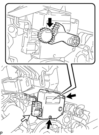
INSTALL AIR OUTLET SERVO MOTOR LH (Face)
-
Install the air outlet servo motor LH (face) with the 2 screws.
-
Connect the connector.
-
Text in Illustration *1 Alignment Marks When reusing the air outlet servo motor LH (face):
Align the moving parts and air conditioning unit as shown in the illustration and install the lever.
-
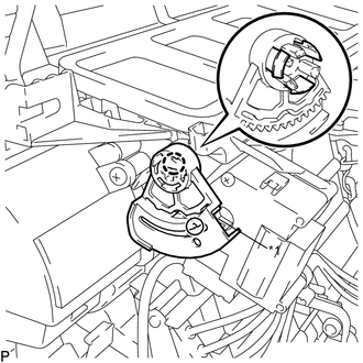
Text in Illustration *1 Cutout Part When using the new air outlet servo motor LH (face):
Set the lever so that the cutout part engages with a tooth of the gear, and then attach the 3 claws to install the lever.
-
-
INSTALL AIR OUTLET SERVO MOTOR RH (Face)
-
Install the air outlet servo motor RH (face) with the 2 screws.
-
Connect the connector.
-
Text in Illustration *1 Alignment Marks When reusing the air outlet servo motor RH (face):
Align the moving parts and air conditioning unit as shown in the illustration and install the lever.
-
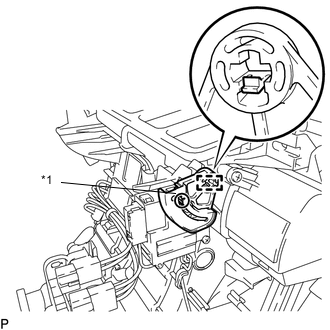
Text in Illustration *1 Cutout Part When using the new air outlet servo motor RH (face):
Set the lever so that the cutout part engages with a tooth of the gear, and then attach the claw to install the lever.
-
-
INSTALL AIR MIX SERVO MOTOR LH (Cool)
-
Make sure that the rod does not rotate further by trying to rotate it clockwise.
-
Install the air mix servo motor LH (cool) with the 2 screws.
-
Connect the connector.
-
-
INSTALL AIR MIX SERVO MOTOR RH (Cool)
-
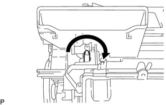
Make sure that the rod does not rotate further by trying to rotate it clockwise.
-
Install the air mix servo motor RH (cool) with the 2 screws.
-
Connect the connector.
-
-
INSTALL COOL AIR BYPASS SERVO MOTOR LH
-
When reusing the cool air bypass servo motor LH:
Align the moving parts and air conditioning unit as shown in the illustration and install the damper servo with the 2 screws.
Text in Illustration *1 Alignment Marks -
When using the new cool air bypass servo motor LH:
Set the lever so that the cutout part engages with a tooth of the gear, and then install the cool air bypass servo motor LH with the 2 screws.
-
Connect the connector.
-
-
INSTALL COOL AIR BYPASS SERVO MOTOR RH
-
When reusing the cool air bypass servo motor RH:
Align the moving parts and air conditioning unit as shown in the illustration and install the damper servo with the 2 screws.
Text in Illustration *1 Alignment Marks -
When using the new cool air bypass servo motor RH:
Set the lever so that the cutout part engages with a tooth of the gear, and then install the cool air bypass servo motor RH with the 2 screws.
-
Connect the connector.
-
-
INSTALL NO. 1 AIR DUCT SUB-ASSEMBLY
-
Attach the 4 claws to install the No. 1 duct sub-assembly.
-
-
INSTALL NO. 2 AIR DUCT SUB-ASSEMBLY
-
Attach the 4 claws to install the No. 2 duct sub-assembly.
-
-
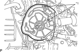
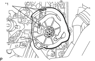
INSTALL BLOWER ASSEMBLY