SOLAR SENSOR(for Front Side) INSPECTION
PROCEDURE
-
INSPECT AUTOMATIC LIGHT CONTROL SENSOR (SOLAR SENSOR)
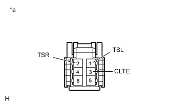
Text in Illustration *a Component without wire harness connected
(Automatic Light Control Sensor (Solar Sensor))
-
Connect the battery's positive (+) lead to terminal 6 and the negative (-) lead to terminal 3, and then measure the voltage according to the value(s) in the table below.
Standard Voltage Tester Connection Condition Specified Condition 1 (TSL) - 3 (CLTE) Sensor subjected to electric light 4.0 to 4.6 V 1 (TSL) - 3 (CLTE) Sensor covered with a cloth 0.8 V or less 2 (TSR) - 3 (CLTE) Sensor subjected to electric light 4.0 to 4.6 V 2 (TSR) - 3 (CLTE) Sensor covered with a cloth 0.8 V or less Note
The connection procedure for using a digital tester such as a TOYOTA electrical tester is shown above.
Tech Tips
-
As the inspection light is moved away from the sensor, the voltage increases.
-
Use an incandescent lamp for inspection. Bring it within 30 cm (11.8 in.) of the A/C solar sensor.
If the result is not as specified, replace the automatic light control sensor (solar sensor).
-
-