AIR CONDITIONING SYSTEM Heater Water Pump Circuit
DESCRIPTION
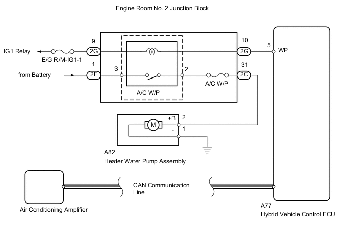
The heater water pump assembly sends engine coolant to the heater core assembly while the engine is stopped to prevent heater effectiveness from becoming low. Directed by the air conditioning amplifier, the hybrid vehicle control ECU operates the water pump relay and drives the heater water pump assembly.
WIRING DIAGRAM
PROCEDURE
-
CHECK DTC (CAN COMMUNICATION SYSTEM)
-
Use the intelligent tester to check if the CAN communication system is functioning normally.
Result Result Proceed to CAN DTC is not output A CAN DTC is output (for LHD) B CAN DTC is output (for RHD) C
B 
GO TO CAN COMMUNICATION SYSTEM Click here
C
GO TO CAN COMMUNICATION SYSTEM Click here
A 
-
-
PERFORM ACTIVE TEST USING INTELLIGENT TESTER (WATER PUMP RELAY)
-
Select the Active Test, using the intelligent tester to generate a control command, and then check that the heater water pump operates.
Air Conditioner Tester Display Test Part Control Range Diagnostic Note Water Pump Water pump relay OFF or ON - Result Result Proceed to Heater water pump operates smoothly A Heater water pump does not operate smoothly B
A
PROCEED TO NEXT CIRCUIT INSPECTION SHOWN IN PROBLEM SYMPTOMS TABLE Click here
B
-
-
INSPECT FUSE (A/C W/P, E/G R/M-IG1-1)
-
Remove the A/C W/P and E/G R/M-IG1-1 fuses from the engine room No. 2 relay block.
-
Measure the resistance according to the value(s) in the table below.
Standard resistance Tester Connection Condition Specified Condition A/C W/P fuse Always Below 1 Ω E/G R/M-IG1-1 fuse
NG
REPLACE FUSE
OK
-
-
CHECK HARNESS AND CONNECTOR (ENGINE ROOM NO. 2 JUNCTION BLOCK - BODY GROUND)
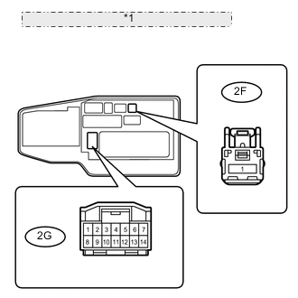
*1 Front view of wire harness connector: (to Engine Room No. 2 Junction Block)
-
Disconnect the 2G and 2F engine room No. 2 junction block connector.
-
Measure the voltage according to the value(s) in the table below.
Standard voltage Tester Connection Condition Specified Condition 2G-9 - Body ground Power switch ON (IG) 11 to 14 V 2F-1 - Body ground Always
NG
REPAIR OR REPLACE HARNESS OR CONNECTOR
OK
-
-
CHECK ENGINE ROOM NO. 2 JUNCTION BLOCK
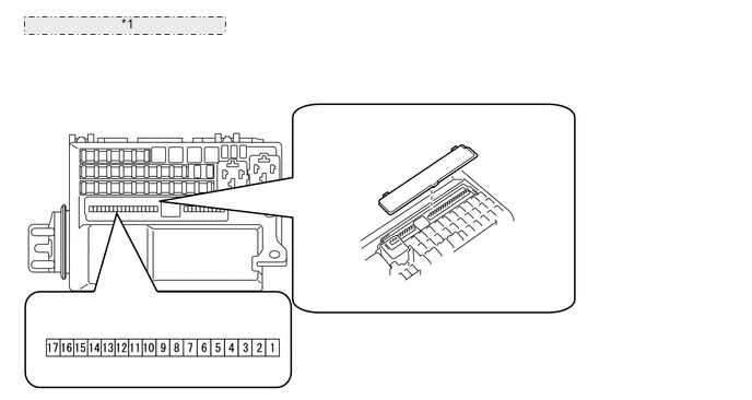
*1 Engine Room No. 2 Junction Block Tech Tips
The A/C W/P relay is an inner circuit of the engine room No. 2 relay block.
-
Remove the terminal cover from the engine room No. 2 junction block.
-
Measure the voltage according to the value(s) in the table below for the A/C W/P relay terminal of the engine room No. 2 relay block.
Standard voltage Tester Connection Condition Specified Condition 2 - Body ground Power switch ON (IG) 11 to 14 V 3 - Body ground Always 11 to 14 V
NG
REPLACE ENGINE ROOM NO. 2 JUNCTION BLOCK
OK
-
-
CHECK HARNESS AND CONNECTOR (ENGINE ROOM NO. 2 JUNCTION BLOCK - HYBRID VEHICLE CONTROL)
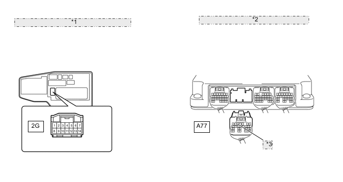
*1 Front view of wire harness connector: (to Engine Room No. 2 Junction Block) *2 Rear view of wire harness connector: (to Hybrid Vehicle Control ECU) *3 WP
-
Disconnect the 2G engine room No. 2 junction block connector.
-
Disconnect the A77 hybrid vehicle control ECU connector.
-
Measure the resistance according to the value(s) in the table below.
Standard resistance Tester Connection Condition Specified Condition A77-5 (WP) - 2G-10 Always Below 1 Ω
NG
REPAIR OR REPLACE HARNESS OR CONNECTOR
OK
-
-
CHECK HARNESS AND CONNECTOR (HEATER WATER PUMP ASSEMBLY - BODY GROUND)
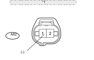
*1 Front view of wire harness connector: (to Heater Water Pump Assembly)
-
Disconnect the A82 heater water pump assembly connector.
-
Measure the resistance according to the value(s) in the table below.
Standard resistance Tester Connection Condition Specified Condition A82-1 (-) - Body ground Always Below 1 Ω
NG
REPAIR OR REPLACE HARNESS OR CONNECTOR
OK
-
-
CHECK HARNESS AND CONNECTOR (ENGINE ROOM NO. 2 J/B - HEATER WATER PUMP ASSEMBLY)
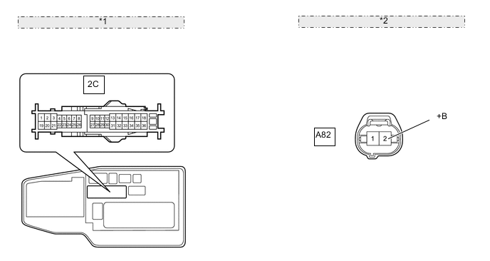
*1 Front view of wire harness connector: (to Engine Room No. 2 Junction Block) *2 Front view of wire harness connector: (to Heater Water Pump Assembly)
-
Disconnect the 2C engine room No. 2 junction block connector.
-
Disconnect the A82 heater water pump assembly connector.
-
Measure the resistance according to the value(s) in the table below.
Standard resistance Tester Connection Condition Specified Condition 2C-31 - A82-2 (+B) Always Below 1 Ω
NG
REPAIR OR REPLACE HARNESS OR CONNECTOR
OK
-
-
INSPECT HEATER WATER PUMP ASSEMBLY
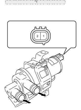
*1 Component without harness connected: (Heater Water Pump Assembly)
-
Disconnect the A82 heater water pump assembly connector.
-
Apply battery voltage to the terminals of the connector, and check the heater water pump operation.
OK Measurement Condition Specified Condition Battery positive (+) - Terminal 2
Battery negative (-) - Terminal 1
Heater water pump operates smoothly Note
Complete this inspection within 10 seconds if there is no water in the heater water pump assembly.
NG
REPLACE HEATER WATER PUMP ASSEMBLY Click here
OK
-
-
REPLACE AIR CONDITIONING AMPLIFIER
-
Replace the air conditioning amplifier with a normal one and check that the condition returns to normal Click here.
OK Same problem does not occur.
OK
END (AIR CONDITIONING AMPLIFIER IS DEFECTIVE)
NG
REPLACE HYBRID VEHICLE CONTROL ECU Click here
-